Electronic Functions
Functional Description
3-22
3.3.3.2
General infomation
about external interfaces
This printer type is equipped with a parallel Centronics type interface (according
IEEE1284) and a internal Ethernet Interface which are mounted on the printer’s main
board. An external modular serial Interface can be installed so the printer is able to
handle 3 Interfaces at a time (Parallel, Serial (ext.) and Ethernet (int.)). Other modular
interfaces (TallyCom, TGNet, Coax, Twinax, etc.) will cause the internal parallel I/O
being switched off.
If an additional parallel I/O is installed, it is compulsory to disable the internal CX I/O
on the main board, so that only the plugged-in modular parallel I/O’s shall be active
in order to avoid misreading data on the parallel data lines: Two parallel I/O’s will not
work together.
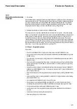
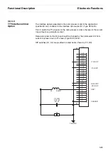
To avoid this the CPU of this printer is monitoring a signal at the connector for external
I/O’s to determine the presence of a second parallel interface plugged in the modular
slot.
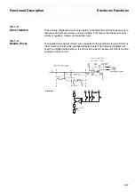
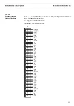
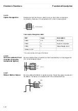
The signal’s name is PT0, it can be found at Pin 15 A of the external I/O connector.
Please refer to the following table to determine the function of PT0:
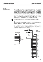
Possible modification of existing and future external I/O’s with own parallel interface:
PTO in Volts
Meaning
< 1.8 Volt
> 1.8 Volt … 2.5 … < 3.0 Volt
> 4.5 Volt
the internal parallel (CX) I/O will be used
the external parallel I/O will be used
the internal parallel (CX) I/O will be used
V
CC
p
u
ll
u
p
p
u
ll down
GND
PT0
Summary of Contents for 2365
Page 1: ...Maintenance manual Matrix printer 2365 2380...
Page 2: ...This page intentionally left blank...
Page 8: ...This page intentionally left blank...
Page 10: ...This page intentionally left blank...
Page 20: ...This page intentionally left blank...
Page 32: ...Mechanical Functions Functional Description 3 12 right mark mark mark...
Page 35: ...Functional Description Electronic Functions 3 15 2365 2380 Electronic groups...
Page 128: ...This page intentionally left blank...
Page 134: ...Mechanical Adjustments Adjustments 6 6...
Page 136: ...Electrical Adjustments Adjustments 6 8...
Page 142: ...Housing Spare Parts and Schematics 7 2 7 1 Housing 7 1 1...
Page 144: ...Basic Printer Spare Parts and Schematics 7 4 7 2 1 Basic Printer 1 3 36...
Page 145: ...Spare Parts and Schematics Basic Printer 7 5 Basic Printer 2 3 462646...
Page 146: ...Basic Printer Spare Parts and Schematics 7 6 Basic Printer 3 3...
Page 151: ...This page intentionally left blank...
Page 164: ...Option Recognition Spare Parts and Schematics 7 24 7 10 Option Recognition...
Page 168: ...This page intentionally left blank...
Page 170: ...Tractor Complete Rear Tractor 2T Model 8 2 8 2 Tractor Complete 4 1...
Page 172: ...This page intentionally left blank...
Page 174: ...Cutting Device Option Specifications 9 2 14 6 4 12 1 5 6 11 7 13 7 8 17 2 9 3 16 15 4...
Page 176: ...This page intentionally left blank...
Page 177: ...2nd Front Tractor option 10 1 10 2nd Front Tractor option...
Page 179: ...Printer Stand Overview 11 1 11 Printer Stand 11 1 Overview...
Page 180: ...Installing the Printer Stand Printer Stand 11 2 11 2 Installing the Printer Stand 1 2 3 4...
Page 181: ...Printer Stand Installing the Printer Stand 11 3 6 8 7 5...
Page 182: ...Installing the Printer Stand Printer Stand 11 4 9 10...


