Electronic Functions
Functional Description
3-28
3.3.5
Printhead Sensor Board
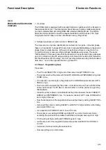
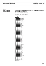
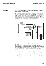
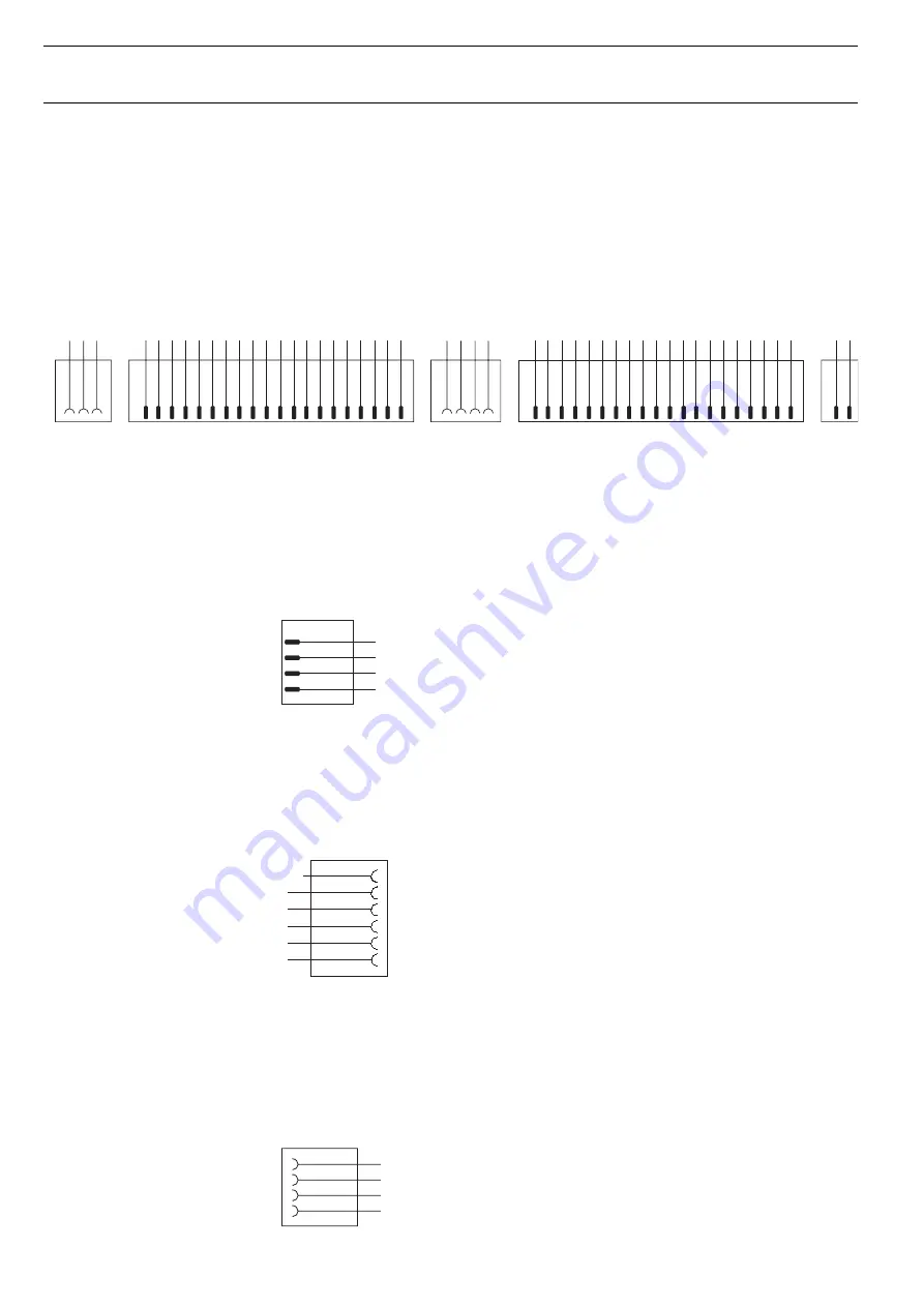
This Board is mounted inside the carriage. It contains connectors for fan (X1) and
AGA-Sensor connector (X2). X3 and X4 will take the printhead cables. X7 is provided
for the clock station. Details in chapter 7.25.
3.3.6
Interlock Switch
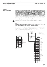
This switch is necessary to prevent injuring the operator if the top flap is open.
In case of opening the top flap the driver voltage will be switched off.
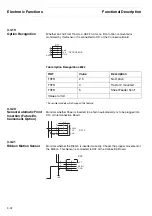
This task is carried out by means of two hall sensors and a built in magnet. The
sensors are connected to X8 Pin 2 and 3 (Signals ISW) at the connector board.
3.3.7
Double Sensor and
Paper Motion Sensor
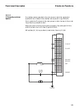
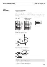
This reflex sensor unit is competent for PE Front Insertion (Sensor V2) and Paper
Position (Sensor V1). The Signals are connected to X7 on the connector board.
For standard assembly only a 4-pin (1-4) connector is mounted.
3.3.8
Sensor Sheetfeeder* and
3rd Tractor
This reflex sensor (GP 2 S 7) is necessary for recognition of Sheetfeeder paper.
Details in chapter 7.31.
This sensor is connected to X9 connector board.
3
2
1
A
G
A
C
C
V
D
N
G
2
X
3
4
2
1
C
C
V
T
W
C
_
A
H
C
D
N
G
T
W
C
C
_
B
H
C
7
X
2
1
1
X
8
1
7
7
1
6
6
1
5
5
1
4
4
1
3
3
1
2
2
1
1
0
1
1
1
9
1
N
U
1
T
FI
H
S
2
E
R
A
P
S
9
N
U
3
N
U
0
1
N
U
1
E
R
A
P
S
1
1
N
U
5
N
U
2
1
N
U
3
X
0
2
9
1
8
7
1
N
5
1
N
8
N
U
2
C
T
P
8
1
N
6
N
U
6
1
N
1
C
T
P
7
N
U
2
T
FI
H
S
8
1
7
7
1
6
6
1
5
5
1
4
4
1
3
3
1
2
2
1
1
0
1
1
1
9
1
2
N
8
N
1
1
N
0
1
N
9
N
7
N
2
1
N
5
N
2
2
N
4
X
0
2
9
1
8
3
1
N
9
1
N
6
N
3
N
0
2
N
1
N
4
1
N
3
2
N
2
N
4
2
N
4
N
4
2
3
1
ISW2
GND
X8
VCC
ISW1
6
5
4
3
2
1
X7
RED
XPW
S
XP
S
E2
XP
S
E1
YCC
GND
Front
s
en
s
or
P
a
Do
ub
le
S
en
s
4
2
3
1
PSE4
DIO3
GND
X9
-Sheet
Feeder
*
For printer models which support this feature
Summary of Contents for 2365
Page 1: ...Maintenance manual Matrix printer 2365 2380...
Page 2: ...This page intentionally left blank...
Page 8: ...This page intentionally left blank...
Page 10: ...This page intentionally left blank...
Page 20: ...This page intentionally left blank...
Page 32: ...Mechanical Functions Functional Description 3 12 right mark mark mark...
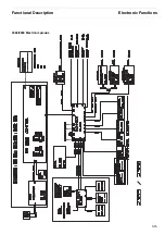
Page 35: ...Functional Description Electronic Functions 3 15 2365 2380 Electronic groups...
Page 128: ...This page intentionally left blank...
Page 134: ...Mechanical Adjustments Adjustments 6 6...
Page 136: ...Electrical Adjustments Adjustments 6 8...
Page 142: ...Housing Spare Parts and Schematics 7 2 7 1 Housing 7 1 1...
Page 144: ...Basic Printer Spare Parts and Schematics 7 4 7 2 1 Basic Printer 1 3 36...
Page 145: ...Spare Parts and Schematics Basic Printer 7 5 Basic Printer 2 3 462646...
Page 146: ...Basic Printer Spare Parts and Schematics 7 6 Basic Printer 3 3...
Page 151: ...This page intentionally left blank...
Page 164: ...Option Recognition Spare Parts and Schematics 7 24 7 10 Option Recognition...
Page 168: ...This page intentionally left blank...
Page 170: ...Tractor Complete Rear Tractor 2T Model 8 2 8 2 Tractor Complete 4 1...
Page 172: ...This page intentionally left blank...
Page 174: ...Cutting Device Option Specifications 9 2 14 6 4 12 1 5 6 11 7 13 7 8 17 2 9 3 16 15 4...
Page 176: ...This page intentionally left blank...
Page 177: ...2nd Front Tractor option 10 1 10 2nd Front Tractor option...
Page 179: ...Printer Stand Overview 11 1 11 Printer Stand 11 1 Overview...
Page 180: ...Installing the Printer Stand Printer Stand 11 2 11 2 Installing the Printer Stand 1 2 3 4...
Page 181: ...Printer Stand Installing the Printer Stand 11 3 6 8 7 5...
Page 182: ...Installing the Printer Stand Printer Stand 11 4 9 10...


