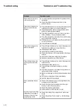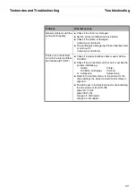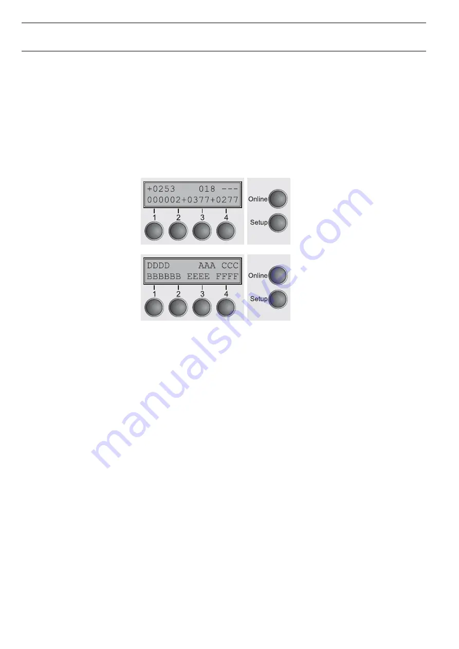
Display Message “Hardware Alarm”
Testmodes and Troubleshooting
4-24
4.6
Display Message
“Hardware Alarm”
To analyse failures much more easier, an extended failure report has been imple-
mented. The messages described below will only occur in “Hardware Alarm” state.
If this message occures the printer must be repaired before switching on again.
Please take care about the fact that in “Hardware Alarm” state the power voltage is
switched off to avoid further damages. Please read also chapter 4.3 “Monitoring
Functions”.
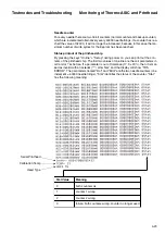
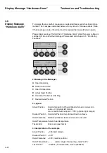
2. Meaning of the Messages
A
Head Clearance
B
Task Control Code
C
Head Temperature
D
Actual Head Position
E
Horizontal Position of AGA Flag
F
Desired Head Position
3. Legend
Actual Position
Horizontal position of the printhead while error occurs min.
value = 0; (physical left margin)
max. value should be approx. 1730; (physical right margin)
Desired Position
Horizontal Position the printhead tried to achieve
Head Clearance
Relative printhead clearance while error occured
Head Temperature Current head temperature
Taskcontrol
Error code (see item 6)
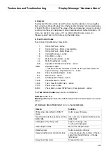
4. Interpretation of the example
Actual Position
= 0253 (left margin)
Desired Position
= 0277
Head Clearance
= 018 (relative position)
Head Temperature = - - - (below range of measuring = head “cold”)
Task control
= 000002 (horizontal task, motor accelerate)
Summary of Contents for 2365
Page 1: ...Maintenance manual Matrix printer 2365 2380...
Page 2: ...This page intentionally left blank...
Page 8: ...This page intentionally left blank...
Page 10: ...This page intentionally left blank...
Page 20: ...This page intentionally left blank...
Page 32: ...Mechanical Functions Functional Description 3 12 right mark mark mark...
Page 35: ...Functional Description Electronic Functions 3 15 2365 2380 Electronic groups...
Page 128: ...This page intentionally left blank...
Page 134: ...Mechanical Adjustments Adjustments 6 6...
Page 136: ...Electrical Adjustments Adjustments 6 8...
Page 142: ...Housing Spare Parts and Schematics 7 2 7 1 Housing 7 1 1...
Page 144: ...Basic Printer Spare Parts and Schematics 7 4 7 2 1 Basic Printer 1 3 36...
Page 145: ...Spare Parts and Schematics Basic Printer 7 5 Basic Printer 2 3 462646...
Page 146: ...Basic Printer Spare Parts and Schematics 7 6 Basic Printer 3 3...
Page 151: ...This page intentionally left blank...
Page 164: ...Option Recognition Spare Parts and Schematics 7 24 7 10 Option Recognition...
Page 168: ...This page intentionally left blank...
Page 170: ...Tractor Complete Rear Tractor 2T Model 8 2 8 2 Tractor Complete 4 1...
Page 172: ...This page intentionally left blank...
Page 174: ...Cutting Device Option Specifications 9 2 14 6 4 12 1 5 6 11 7 13 7 8 17 2 9 3 16 15 4...
Page 176: ...This page intentionally left blank...
Page 177: ...2nd Front Tractor option 10 1 10 2nd Front Tractor option...
Page 179: ...Printer Stand Overview 11 1 11 Printer Stand 11 1 Overview...
Page 180: ...Installing the Printer Stand Printer Stand 11 2 11 2 Installing the Printer Stand 1 2 3 4...
Page 181: ...Printer Stand Installing the Printer Stand 11 3 6 8 7 5...
Page 182: ...Installing the Printer Stand Printer Stand 11 4 9 10...

