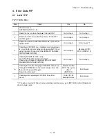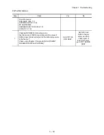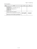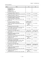
1 – 4
Chapter 1 Troubleshooting
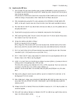
1.4 Cautions for FIP Use
1) The FIP makes the assumption that the printer controller (PWBA ESS) is functioning normally. If
the problem cannot be corrected by using the FIP, replace the printer controller with a new one and
check for proper operation.
If the trouble is not still corrected, replace the major parts and then related parts in succession and
confirm according to the procedures of the "Initial check" and "Major check parts".
2) When troubleshooting using the FIP, parts substitution of the HVPS/MCU, FUSER ASSY, BTR
ASSY or other parts may be necessary for fault isolation. Have these parts available in advance.
3) The initial checks in the FIP only checks items which are most likely to cause the problem and can
be quickly eliminated.
4) Check both the major parts as well as any related sub-components in the initial checks.
5) When working with the printer, be sure to remove the power cord. If a check requires the power to
be connected, never touch any live parts.
6) Connector condition is denoted as follows:
[P/J12]
→
Connector (P/J12) is connected.
[P12]
→
Plug side of the connector (P/J12) removed (except when attached directly to the board).
[J12]
→
Jack side of the connector (P/J12) removed (except when attached directly to the board).
7) [P/J1- 2(+) and P/J3-4(-)] in the FIP means taking a measurement with the plus side of the meter
connected to [P/J1, Pin 2] and the minus side to [P/J3, Pin 4].
8) [P/J1 -> P/J2] in the FIP means measurement for all terminals corresponding between [P/J1] and
[P/J2] as shown in the "Wire connecting diagram".
9) In [P/J1- 2 (+) and P/J3-4 (-)] in the FIP where voltage is measured, [P/J3-4 (-)] is always at the AG
(analog ground), SG (signal ground), or RTN (return).
Therefore, after verifying ground between AGs, SGs, or RTNs respectively, the minus side can be
connected to the PIN of AG, SG or RTN instead of [P/J3-4 (-)].
However, care should be taken not to mistake since [AG], [SG], and [RTN] are not on the same
level.
10) Measure the voltage of small connectors with the special tool. Handle the tool with care, as the
leading edge of the tool is pointed.
11) When measuring a voltage, ensure that the EP CARTRIDGE, BRT ASSY and paper tray are prop-
erly seated. Close the COVER TOP ASSY, FUSER ASSY, and COVER REAR and switch the
printer power ON.
12) Voltages in the FIP are nominal. If the values fall within a tolerance of +/- 10%, they should be con-
sidered acceptable.
13) Parts which are routinely checked, as indicated in the FIP, and without any specific removal proce-
dures, should be handled carefully.
Summary of Contents for 9045N
Page 1: ...Laser Printer TallyGenicom 9045N Service Manual J20006AA ...
Page 16: ...xv Blank Page ...
Page 20: ...Chapter 1 Troubleshooting Chapter 1 Troubleshooting CONTENTS Blank Page ...
Page 88: ...1 68 Chapter 1 Troubleshooting Blank Page ...
Page 160: ...1 140 Chapter 1 Troubleshooting Blank Page ...
Page 162: ...1 142 Chapter 1 Troubleshooting Blank Page ...
Page 164: ...Chapter 2 Printer Diagnostics Chapter 2 Diagnostics CONTENTS 11 Print Summary 2 16 ...
Page 194: ...1 10 Chapter 3 Removal and Replacement Procedures RRPs RRP2 150 PAPER CASSETTE ...
Page 213: ...1 29 Chapter 3 Removal and Replacement Procedures RRPs RRP3 550 PAPER CASSETTE ...
Page 240: ...1 56 Chapter 3 Removal and Replacement Procedures RRPs RRP4 150 paper Feeder ...
Page 257: ...1 73 Chapter 3 Removal and Replacement Procedures RRPs RRP5 550 Paper Feeder ...
Page 277: ...1 93 Chapter 3 Removal and Replacement Procedures RRPs RRP6 Xerographics ...
Page 302: ...1 118 Chapter 3 Removal and Replacement Procedures RRPs RRP7 500 Paper Exit ...
Page 322: ...1 138 Chapter 3 Removal and Replacement Procedures RRPs RRP8 Frame Drive ...
Page 331: ...1 147 Chapter 3 Removal and Replacement Procedures RRPs RRP9 Electrical ...
Page 394: ...1 210 Chapter 3 Removal and Replacement Procedures RRPs ...
Page 454: ...1 270 Chapter 3 Removal and Replacement Procedures RRPs Blank Page ...
Page 459: ...4 3 Chapter 4 Plug Jack P J Connector Locations Blank Page ...
Page 465: ...4 9 Chapter 4 Plug Jack P J Connector Locations 3 2 OCT Option P J Diagram ...
Page 468: ...4 12 Chapter 4 Plug Jack P J Connector Locations Blank Page ...
Page 470: ...Chapter 5 Parts Lists Chapter 5 Parts Lists CONTENTS Blank Page ...
Page 479: ...5 9 Chapter 5 Parts List Blank Page ...
Page 483: ...5 13 Chapter 5 Parts List Blank Page ...
Page 490: ...5 20 Chapter 5 Parts List PL 7 2 500 PAPER EXIT 2 2 OPTION FACE UP TRAY ILLUSTRA TION ...
Page 496: ...5 26 Chapter 5 Parts List OPTIONS PL 10 1 OPTION DUPLEX ILLUSTRATION ...
Page 501: ...5 31 Chapter 5 Parts List Blank Page ...
Page 529: ...6 19 Chapter 6 Principles of Operation J26119AA EP CARTRIDGE BTR ASSY ...
Page 531: ...6 21 Chapter 6 Principles of Operation LD Assembly JG6121AA SOS PWB Scanner Assembly ...
Page 535: ...6 25 Chapter 6 Principles of Operation ...
Page 558: ...6 48 Chapter 6 Principles of Operation Blank Page ...
Page 584: ...7 24 Chapter 7 Wiring Diagrams and Signal Information Blank Page ...
Page 608: ...Chapter 9 ESS Options Chapter 9 Controller ESS Options Contents Blank Page ...


