8 - 11
Chapter 8 Printer Specifications
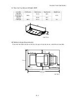
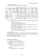
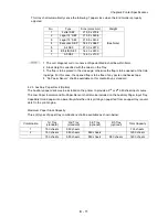
This tray shall automatically sense the following 7 paper sizes when the End Guide is properly
adjusted.
:
1. The curl, diagonal curl or concave of Special Media shall be within 5mm.
2. Stack Height is specified with the Label on the Tray.
3. The flap is to be placed in the side edge; otherwise the flap is to be opened at the trail-
ing edge. For this case, the opened flap is to be free of any paste or adhesive tape.
4. “No Paper Sensor” shall be available on this media tray as standard
4.2.3 Auxiliary Paper Deck (Option)
The Auxiliary paper deck may be installed on the printer to provide a 3
rd
or 4
th
550 sheet input source.
The Low Paper Indicator and No Paper Sensor shall also be included on the Auxiliary Paper Input Tray.
Capability to load paper into a lower tray while the unit is printing on paper fed from an upper tray is avail-
able fro the print engine.
Maximum Paper Stack Capacity
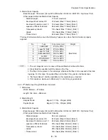
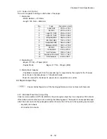
Three (3) types of paper tray combinations shall be available as shown below:
No.
Type
Size (mm x mm)
Weight
1
Letter SEF
215.9 x 279.4
(See Note)
2
Legal 14” SEF
215.9 x 355.6
3
Legal 13” SEF
215.9 x 330.2
4
Executive SEF
184.2 x 266.7
5
A4 SEF
210.0 x 297.0
6
B5 (JIS) SEF
182.0 x 257.0
7
A5 SEF
148.0 x 210.0
Combination
1st Tray
(standard)
2nd Tray
(standard)
3rd Tray
(optional)
4th Tray
(optional)
Total Capacity
1
150 sheets
550 sheets
700 sheets
2
150 sheets
550 sheets
550 sheets
-
1250 sheets
150 sheets
550 sheets
550 sheets
550 sheets
1800 sheets
Summary of Contents for 9045N
Page 1: ...Laser Printer TallyGenicom 9045N Service Manual J20006AA ...
Page 16: ...xv Blank Page ...
Page 20: ...Chapter 1 Troubleshooting Chapter 1 Troubleshooting CONTENTS Blank Page ...
Page 88: ...1 68 Chapter 1 Troubleshooting Blank Page ...
Page 160: ...1 140 Chapter 1 Troubleshooting Blank Page ...
Page 162: ...1 142 Chapter 1 Troubleshooting Blank Page ...
Page 164: ...Chapter 2 Printer Diagnostics Chapter 2 Diagnostics CONTENTS 11 Print Summary 2 16 ...
Page 194: ...1 10 Chapter 3 Removal and Replacement Procedures RRPs RRP2 150 PAPER CASSETTE ...
Page 213: ...1 29 Chapter 3 Removal and Replacement Procedures RRPs RRP3 550 PAPER CASSETTE ...
Page 240: ...1 56 Chapter 3 Removal and Replacement Procedures RRPs RRP4 150 paper Feeder ...
Page 257: ...1 73 Chapter 3 Removal and Replacement Procedures RRPs RRP5 550 Paper Feeder ...
Page 277: ...1 93 Chapter 3 Removal and Replacement Procedures RRPs RRP6 Xerographics ...
Page 302: ...1 118 Chapter 3 Removal and Replacement Procedures RRPs RRP7 500 Paper Exit ...
Page 322: ...1 138 Chapter 3 Removal and Replacement Procedures RRPs RRP8 Frame Drive ...
Page 331: ...1 147 Chapter 3 Removal and Replacement Procedures RRPs RRP9 Electrical ...
Page 394: ...1 210 Chapter 3 Removal and Replacement Procedures RRPs ...
Page 454: ...1 270 Chapter 3 Removal and Replacement Procedures RRPs Blank Page ...
Page 459: ...4 3 Chapter 4 Plug Jack P J Connector Locations Blank Page ...
Page 465: ...4 9 Chapter 4 Plug Jack P J Connector Locations 3 2 OCT Option P J Diagram ...
Page 468: ...4 12 Chapter 4 Plug Jack P J Connector Locations Blank Page ...
Page 470: ...Chapter 5 Parts Lists Chapter 5 Parts Lists CONTENTS Blank Page ...
Page 479: ...5 9 Chapter 5 Parts List Blank Page ...
Page 483: ...5 13 Chapter 5 Parts List Blank Page ...
Page 490: ...5 20 Chapter 5 Parts List PL 7 2 500 PAPER EXIT 2 2 OPTION FACE UP TRAY ILLUSTRA TION ...
Page 496: ...5 26 Chapter 5 Parts List OPTIONS PL 10 1 OPTION DUPLEX ILLUSTRATION ...
Page 501: ...5 31 Chapter 5 Parts List Blank Page ...
Page 529: ...6 19 Chapter 6 Principles of Operation J26119AA EP CARTRIDGE BTR ASSY ...
Page 531: ...6 21 Chapter 6 Principles of Operation LD Assembly JG6121AA SOS PWB Scanner Assembly ...
Page 535: ...6 25 Chapter 6 Principles of Operation ...
Page 558: ...6 48 Chapter 6 Principles of Operation Blank Page ...
Page 584: ...7 24 Chapter 7 Wiring Diagrams and Signal Information Blank Page ...
Page 608: ...Chapter 9 ESS Options Chapter 9 Controller ESS Options Contents Blank Page ...


