

Publication No. GEG-99197
May 04
5-20
TallyGenicom mL450 Laser Printer User Manual
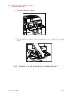
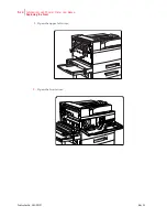
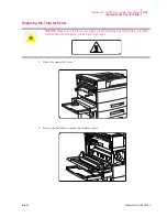
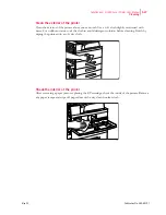
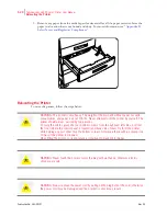
Replacing the Feed Rollers
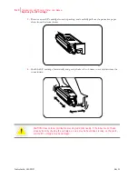
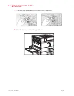
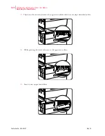
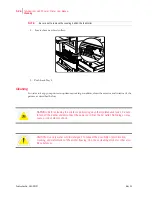
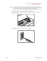
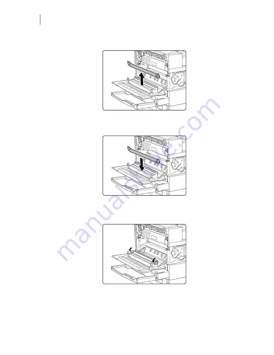
3.
Remove the transfer roller.
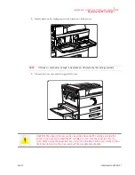
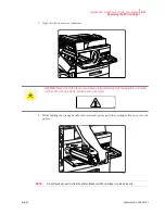
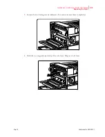
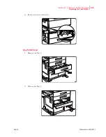
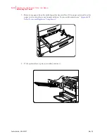
4.
Insert a new transfer roller and press down to hold the roller in place.
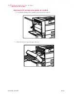
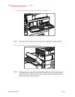
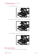
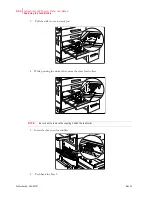
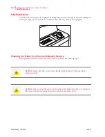
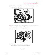
5.
Push the handles to lock the transfer roller in place.
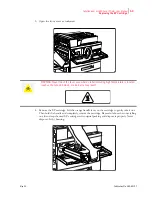
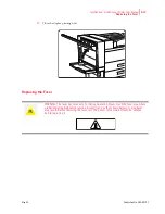
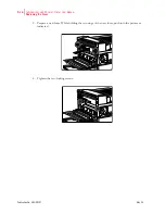
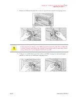
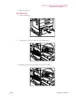
Replacing the Feed Rollers
After replacing the fuser, be sure to also replace the feed rollers.


