6
(a)
(b)
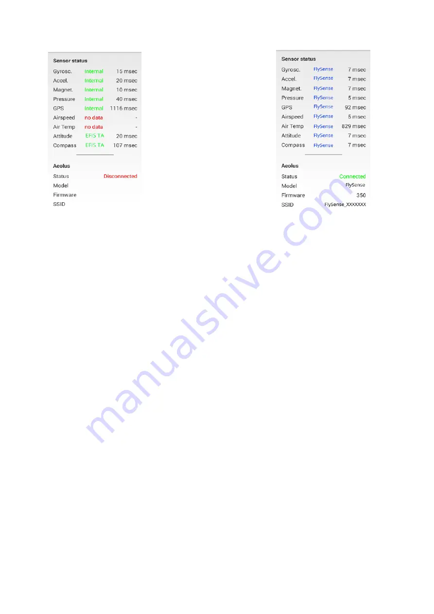
Figure 3 : Sensor status window. (a) EFIS TA app working with internal sensors only, (b)
EFIS TA app connected to a FlySense AoA PRO.
To test the connection, start the EFIS TA app and t ap on “MENU” button a n d t h e n
“Sensor Status”. A screen as in Fig. 3b verifies connection to FlySense AoA PRO. If a screen as in
Fig. 3a comes us, no connection with a FlySense AoA PRO is established. Connection of the smart
mobile device to a FlySense AoA PRO is achieved by two means: (a) wired connection via a USB
cable-adaptor, (b) wireless connection via wifi.
USB Cable Connection
The FlySense AoA PRO comes with a USB connector at the front panel of the device, which
connects it to the smart mobile device that is used as display. USB cable connection confirms
secure communication under any conditions and also facilitates charging of the smart mobile
device.
Please note that in USB Cable connection, the smart mobile device is charged by the
FlySense AoA PRO; accordingly, battery-life of the latter will be reduced if not connected
to an external power source (e.g. cigarette lighter)
.
Please note that due to limitations of the GDL90 communication protocol, ADSB works only
with the wifi connection.
After connection of FlySense AoA PRO to the smart mobile device has been established, please
follow the same steps as when connecting the latter device to a computer. You must permit the
device to connect to unknown sources and press allow when asked, if you trust the connection to
the FlySense AoA PRO.


