20
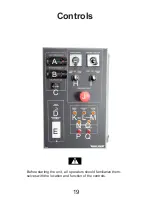
A.
Digital Display:
This system monitors the temperature of the
glycol in the reservoir and entering the circula-
tion manifold. It is shown on the digital display.
B.
Return Temperature:
This gage monitors and displays the tempera-
ture of the glycol in the return manifold. It func-
tions only when the field pump is running.
C.
Total Operating Time:
This hour meter displays the total time that
power is provided to the heater loop.
D. Circuit Breaker:
Under normal operation, circuit breaker is de-
pressed. If circuit breaker load is exceeded, it
will trip the breaker and extend.
E.
Ground Fault Interrupter:
This interrupter circuit monitors the power flow
through the system and trips or breaks the cir-
cuit when there is a ground or short. Correct
the condition, depress the red button to reset
interrupter and resume work.
F.
Circuit Power:
This 2 position rotary switch controls the power
to circuit. Turn the switch clockwise to turn the
power to circuit on and counterclockwise for off.
The circuit power light will come on when the
power is turned on. The burner oil preheater
comes on to preheat the nozzle.
G.
Hose Reel Direction:
This 2 position rotary switch selects the direc-
tion of hose reel operation. Turn the switch fully
clockwise to extend the hose and counterclock-
wise for retracting.
H.
Hose Reel/Field Loop Selector Switch:
This 3 position rotary switch selects the system
that will be supplied with power. Turn fully coun-
terclockwise to select the hose reel system.
Move the switch to its vertical position to turn
off. Turn fully clockwise to provide power to the
field loop system. In this position, the field pump
light will come on.
I.
Compressor/Heater Loop Selector Switch:
This 3 position rotary switch selects the system
that will be supplied with power. Turn fully coun-
terclockwise to select the (compressor system).
When this system is turned on, the compressor
light will come on. Move the switch to the vertical
position to turn off. Turn fully clockwise to turn
the heater loop circuit on. When this system is
turned on, the burner start-up sequence starts.
First, the circulation pump light comes on as
the pump starts. Then the burner igniter starts.
When that burner is operating, the burner flame
light comes on.
J.
Emergency Stop:
This 2 position push-pull switch controls the
power to the machine. Push the switch in to stop
all machine functions and pull out to provide
power. It is recommended that all controls be
placed in their off position before the switch is
pulled out and power restored.
K. Circuit Power:
This light comes on when the power is turned on
and everything is functioning normally. It goes
out when the breaker or interrupter trips or the
power is turned off.
L.
Circulation Pump:
This light comes on when the burner coil cir-
culation pump is on, and the pump is creating
pressure, and goes out when the pump is off.
M.
Burner Flame:
This light comes on when the main burner is on.
The light goes out when the main flame goes
out.Light is not on when pilot is lit.
N.
Field Pump:
This light comes on when the field pump is
turned on and goes out when the pump is off.
O.
Compressor:
This light comes on when there is power to the
compressor and goes out when the power is off.
Warning Indicators:
P.
Low Glycol:
This left red light comes on when the glycol
reservoir level goes below the switch level
and goes off when the level is above. Stop
unit immediately and add glycol to the reser-
voir when this light comes on. Do not over
fill reservoir.
Q.
Overtemp:
This right red light come on when the burners
are on with no call for heat.

