14
tightly grip the gauge, then wheel adjustment is
called for.
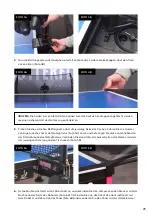
To adjust the wheels, push the gauge into the
end of the Ball Tube where the ball comes out so
it is held rigidly in place. Then use the 4 mm hex
wrench found in the accessories to loosen the
hex screw near the cover of the motor (see Photo
8B). Now move the motor (gripping its cover)
either towards or away from the gauge until the
wheel barely touches it (see Photo 8C). Lastly,
tighten the 4 mm hex screw to hold the wheel in
place. Do this with all 3 motors.
Please note:
The diameter of the adjusting tube is 35 mm, which is the ideal amount of space among the
3 wheels. The robot functions correctly up to a diameter of 37-38 mm.
Replacing The Wheels
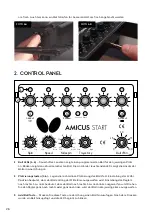
When the wheels can’t be adjusted anymore, or the special coating on the wheels has worn off, the
wheels should be replaced. To do so, start with the lower wheel. Using the smaller 2 mm hex wrench,
loosen the small setscrew that holds the wheel onto the shaft of the motor (see Photo 9A) Before tak-
ing it off, check and memorize the exact position of the wheel on the shaft of the motor. Pull the wheel
off the motor shaft and remove the three #1 Phillips screws that hold the foam wheel onto the hard
plastic hub. Remove the wheel from the hub and replace with a new wheel. Then refasten the hub to the
wheel. Slip the wheel assembly onto the motor shaft until the position of the original wheel is reached.
Tighten the setscrew.
Now manually spin the wheel to be sure it is not rubbing on any surface. If so, loosen the setscrew
and slightly move the wheel’s position on the shaft and try again until the wheel no longer rubs on any
surface. Lastly, tighten the setscrew securely.
For the upper motors, the procedure is a little bit different. Begin by removing the 4 mm hex adjust-
ment screw (see Photo 9B). Grab a hold of the motor cover, and pivot the entire motor mechanism away
from the Ball Tube (see Photos 9C & 9D). Now you can remove the old wheel and push the new wheel
on the motor shaft, and then refasten the wheel onto the motor shaft using the same procedures as
described above for the lower wheel, then replace and tighten the 4 mm hex screw.
The wheel may not be as easy to remove from the shaft, or put back on the shaft, due to the close prox-
imity of the Head Panel and the Oscillation & Trajectory Motor Cover. But because the wheels are foam,
the wheel can be removed and replaced with a little force to bend the foam out of place. If removing
the wheel is too difficult, you can remove the Oscillation and Trajectory Motor Cover to provide more
room for wheel removal and replacement.
Even if only one of the upper wheels has been damaged, we recommend replacing all upper wheels at
once, to ensure the robot does not become inaccurate After replacing wheels, adjust the wheel spacing
as described in the previous section, Checking and Adjusting Wheel Clearance.
Photo 8C
Summary of Contents for AMICUS START
Page 1: ...1 AMICUS START Table Tennis Robot Owner s Manual Bedienungsanleitung Manuel d utilisation ...
Page 19: ...19 ...
Page 21: ...21 Owner s Manual Bedienungsanleitung Manuel d utilisation AMICUS START Tischtennis Roboter ...
Page 40: ...40 ...
Page 42: ...42 ...
Page 62: ...62 ...


