background image

© 

T.A. Morrison & Co. Inc., 2017

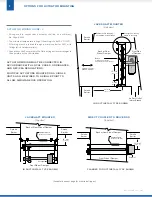
BELIMO FSNF 120

12" max

(305 mm)

Back or Rear

Side of Damper

Front Side

of Damper

24" max

(610 mm)

AIRFLOW

Smoke

Barrier

Sealant or fire stopping,
as required by local codes


Brace

Provided when section

height exceeds 37.5" 

(953 mm)

6" max

(152 mm)

See specific mounting 
details on next page


Smoke

Barrier

Air Duct Outlet:

Inlet or Branch

Sealant/Caulk

(Around perimeter)

Smoke

Barrier

Smoke

Barrier

24" max

(610 mm)

Back or Rear Side of Damper

Front Side of Damper

Actuator

IN DUCT INSTALL TYPE SHOWN

JACKSHAFT MOUNTED

(side view)

FLANGED TO DUCT INSTALL TYPE SHOWN

DIRECT COUPLED TO DRIVE ROD

(top view)

IN DUCT INSTALL TYPE SHOWN

JACKSHAFT MOUNTED

(top view)

ACTUATOR WIRING MUST BE CONNECTED IN 
ACCORDANCE WITH LOCAL CODES, ORDINANCES, 
AND NEC/CSA REGULATIONS.

MULTIPLE ACTUATORS MOUNTED ON A SINGLE 
UNIT SHALL BE WIRED TO A SINGLE POINT TO 
ALLOW SIMULTANEOUS OPERATION.

OPTIONS FOR ACTUATOR MOUNTING

2

ACTUATOR WIRING GUIDE:  

&


>

Wiring used to connect each actuator shall be, as a minimum, 

No. 16 ga. AWM. 


>

The minimum temperature rating of the wiring is to be 302°F 

(150°C)

.


>

All wiring must be routed through a metal conduit or EMT, with 

fittings (all UL Listed materials). 


>

Connections shall occur within the field wiring enclosures integral to 

the operators or the UL Listed box.

(See details on next page for other install types.)

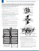
Actuator

Smoke

Barrier

Back or Rear Side of Damper

Front Side of Damper

Sealant/Caulk

(Around perimeter)

Smoke

Barrier

24" max

(610 mm)

Summary of Contents for 1000 SM Series

Page 1: ...e provided if the damper actuator is mounted inside the duct GENERAL INSTALLATION NOTES Smoke dampers must be installed square and free from racking to ensure proper operation and performance Dampers must be installed without stretching or compression to allow them to maintain their original factory adjustment thereby retaining their low leakage rating TAMCO Smoke Dampers are approved to be instal...

Page 2: ...LL TYPE SHOWN JACKSHAFT MOUNTED top view ACTUATOR WIRING MUST BE CONNECTED IN ACCORDANCE WITH LOCAL CODES ORDINANCES AND NEC CSA REGULATIONS MULTIPLE ACTUATORS MOUNTED ON A SINGLE UNIT SHALL BE WIRED TO A SINGLE POINT TO ALLOW SIMULTANEOUS OPERATION OPTIONS FOR ACTUATOR MOUNTING 2 ACTUATOR WIRING GUIDE Wiring used to connect each actuator shall be as a minimum No 16 ga AWM The minimum temperature ...

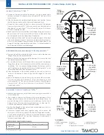
Page 3: ... dimensions are identical c Run a bead of silicone caulk around the perimeter of the damper flange face where it will come into contact with the substrate upon installation This is to prevent leakage between the damper and the wall Caulking may be applied at this step or following step e once the smoke damper has been fastened in place d Place the damper in the desired location on the wall so that...

Page 4: ...ont label and back rear side of damper assemblies c Attach each joiner to the damper frame members using as a minimum four 8 sms screws or rivets as shown in Figures A B d Install the bridge bracket connecting the lower sections Place the bridge bracket so that it is centered over the joint where all four damper sections meet e Fasten the Bridge Bracket in place using 20 bolts making sure they are...

Reviews:

Related manuals for 1000 SM Series