©
T.A. Morrison & Co. Inc., 2017
INSTALLATION PROCEDURES FOR | MULTI-SECTION SMOKE DAMPER ASSEMBLIES
4
INSTRUCTIONS BELOW ARE IN ADDITION TO APPLICABLE INSTALL TYPE INSTALLATION PROCEDURES.
MULTIPLE SECTION SMOKE DAMPER ASSEMBLIES SHOULD BE INSTALLED USING SAME FASTENERS AND
FASTENING PATTERNS AS DESCRIBED IN THE INSTRUCTIONS FOR SINGLE-SECTION SMOKE DAMPERS.
9
/
16
"
(14.3 mm)
±
1
/
8
"
(3.2 mm)
Min. #8 sms Screw
or 3/16" Rivet
2"
(610 mm)
(
±¼"
(6.4 mm)
)
Damper
Frame
Damper
Frame
Joiner
Min. #8
sms Screw, or
3
/
16
”
(4.8 mm)
Rivet
FIG. A
(front view)
Min. ¼”
(6.4 mm)
Bolt/Nut,
#8 sms Screw, or
3
/
16
”
(4.8 mm)
Rivet,
2” (+/- ¼“)
[51 mm (+/- 6 mm)]
from each end of the damper.
Damper
Blade
Damper
Linkage
Damper
Frame
¼"-20
Bolt/Nut
Jackshaft Linkage
(if provided)
Rivet Nuts
(inserted into frame)
Bridge
Min. 14”
(355 mm)
long,
secured with ¼"
(6.4 mm)
bolts
FIG. C
(top view)
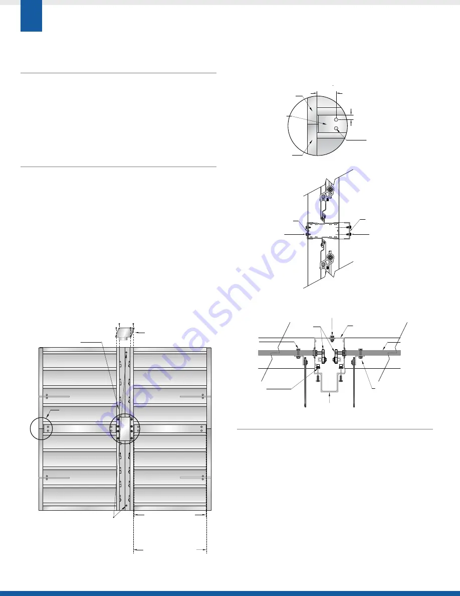
ASSEMBLING SMOKE DAMPERS THAT ARE
MULTIPLE SECTIONS HIGH:
a. Slide joiners over frame members, where top and bottom sections
meet.
b. Joiners must be secured to both the front (label) and back (rear) side
of damper assemblies.
c. Attach each joiner to the damper frame members using, as a minimum,
four #8 sms screws or rivets as shown in Figures A & B.
ASSEMBLING SMOKE DAMPERS THAT ARE
MULTIPLE SECTIONS HIGH AND MULTIPLE
SECTIONS WIDE:
a. Slide joiners over frame members, where top and bottom sections
meet.
b. Joiners must be secured to both the front (label) and back (rear) side
of damper assemblies.
c. Attach each joiner to the damper frame members using, as a
minimum, four #8 sms screws or rivets as shown in Figures A & B.
d. Install the bridge bracket connecting the lower sections. Place the
bridge bracket so that it is centered over the joint where all four
damper sections meet.
e. Fasten the Bridge Bracket in place, using ¼"-20 bolts, making sure
they are secured in the pre-set, factory-supplied rivet nut holes.
MULLION END CAPS
FOR FLANGED TO DUCT INSTALL TYPE,
MULTI-SECTION DAMPER INSTALLATIONS
>
Mullion end caps are provided with all multi-section dampers
that are to be installed as Flanged to Duct Install Type.
>
These are required to prevent air flow from passing through
open channels. (Mullion end caps are not intended for use as
structural support.)
>
Caulk surfaces between mullion end caps and damper frame for
an airtight seal.
>
Mullion end caps are not required for In Duct and Extended Rear
Flange Install Type dampers. As such they are not provided as
standard, but are available for order as separate parts.
Joiner
Joiner
Min. #8
sms Screw, or
3
/
16
”
(4.8 mm)
Rivet
Min. #8
sms Screw, or
3
/
16
”
(4.8 mm)
Rivet
FIG. B
(side view)
Joiner
Damper Section ID
Joiner width =
Damper Section ID
Less 0.5”
(12.7 mm)
(± 0.125”
(3 mm)
)
(See Fig. A & B
Details)
Bridge Bracket centered
where sections meet
(See Fig. C Detail)
Frame members are designed
to overlap and are manufactured
with aligned positioning holes.
When dampers are positioned
correctly, holes will be aligned.
Joiner
Mullion End Cap
(at top and bottom)


