background image

tams 

elektronik

Manual 

BiDiBooster

Item no.  40-19507

t

a

ms elektronik

n n n

Summary of Contents for BiDiBooster

Page 1: ...t a m s e l e k t r o n i k Manual BiDiBooster Item no 40 19507 tams elektronik n n n...

Page 2: ...ng the control unit 18 6 3 Connection of a BiDiB interface 20 6 4 Connection of additional boosters 20 6 5 Connecting the tracks 22 6 6 Connecting the power supply 22 7 Settings 23 7 1 Programming via...

Page 3: ...ny form or by any means electronic or mechanical including photocopying without prior permission in writing from Tams Elektronik GmbH Subject to technical modification RailCom is the registered tradem...

Page 4: ...in order to prevent damages at rails and vehicles In layouts monitored by RailCom the booster also provides the so called RailCom cutout needed to transfer RailCom feedback data You can measure the po...

Page 5: ...roblems in the future If you pass the booster on to another person please pass on the manual with it Intended use The BiDiBooster is designed to be operated according to the instructions in this manua...

Page 6: ...ormer s voltage Desired track voltage Recommended transformer s voltage AC voltage DC voltage 10 12 V 12 V desired track voltage 2 V 12 15 V 15 V 15 18 V 16 V 18 22 V 18 V 22 V 20 V Determining the tr...

Page 7: ...circuit to another voltage than specified impermissibly high humidity and condensation build up can cause serious injury due to electrical shock Take the following precautions to prevent this danger...

Page 8: ...Volt digital voltage Power max 120 Watt Digital formats DCC Motorola mfx control commands only Feedback logs RailCom BiDiB Interfaces DCC conforming booster port 3 pole BiDiB port RJ 45 Track signal s...

Page 9: ...r boosters either via the DCC conforming booster port 3 pole or the BiDiB port RJ 45 You can configure the BiDiBooster that way a closed circuit connection is made between the DCC conforming booster p...

Page 10: ...tion due to sending the RailCom cutout is impossible on principle Integrated global RailCom detector There is a global RailCom detector integrated in the BiDiBooster receiving the decoders feedback si...

Page 11: ...n DCC controlled layouts The DCC input of the BiDiBooster is isolated through an opto coupler Balanced track voltage The BiDiBooster provides a regulated track voltage which can be set to a value betw...

Page 12: ...the DCC control unit when a short circuit occurs and then the control unit switches off the booster The short circuit sensitivity or the interrupting current can be set to 2 3 or 4 A In order to preve...

Page 13: ...y for safety reasons Possible causes Hindrance to the flow of air through the ventilation slits Significantly higher rated voltage of the transformer than the set track voltage in combination with a h...

Page 14: ...hort circuit protection switches off the booster immediately Thus putting the layout into operation can be difficult with an active short circuit protection The BiDiBooster is able to supply an increa...

Page 15: ...n at the same time The following divisions are useful station engine sheds the main lines if necessary in several sections the branch lines if necessary in several sections Make sure that section bord...

Page 16: ...alternative 1 C data D earth data E short circuit feedback line B Connections to the transformer and the tracks 1 transformer 2 transformer 3 outer conductor left rail 4 middle conductor right rail C...

Page 17: ...e BiDiB protocol With BiDiBoosters installed at the end of a BiDi bus line i e with only one branching RJ 45 cable you have to mount the terminating jumpers JP5 and JP6 according fig 4 In state of del...

Page 18: ...the BiDiB port you have to alter the settings section 7 Connection A DCC conforming 3 pole port Via the connection A you can connect the booster either to the control unit s DCC booster connection or...

Page 19: ...iB port RJ 45 Via the connection C optionally C1 or C2 you can connect the BiDiBosster with RJ 45 cables to the BiDiB interface of your control unit or a PC interface with track output Hint If necessa...

Page 20: ...ect the control unit via the 3 pole DCC booster port and additional boosters via RJ 45 cables to the BiDiB port In this case the BiDiBooster has to be set accordingly section 7 Then a closed circuit c...

Page 21: ...g jumpers section 6 1 Please note When using this connection version you have to connect all additional booster via the BiDiB port It is not possible to make a connection from the BiDiB port to the DC...

Page 22: ...If you have then please note The left pole of the second booster s track port has to be connected to the same rail as the left pole of the booster already connected The same goes of course for the ri...

Page 23: ...Autostarting time after a short circuit 4 10 sec to be set in 1 sec steps 4 sec no Max track current interrupting current after a short circuit 2 4 A to be set in 1 A steps 3 A yes RailCom active or...

Page 24: ...the RJ 45 booster port DCC interface yes 7 1 Programming via BiDiB As soon as the BiDiBooster is connected to a BiDiB controlled and monitored layout it is integrated automatically into the PC layout...

Page 25: ...or CV 7 version After having started the programming mode input the value 62 for CV 7 the LED flashes quickly with a yellow light You can now alter the booster s settings by choosing CV 7 again and in...

Page 26: ...inactive Determining the interface 53 BiDiB booster port 54 DCC booster port 55 Reception of the booster signals via the DCC booster port and transmission via the RJ 45 booster port Switching off with...

Page 27: ...points address to release the watchdog funtion Condition Watchdog funtion active Autostarting time after 5 short circuits Default value 60 sec 100 set autostarting time after a short circuit 101 10 s...

Page 28: ...g jumpers Before inserting the jumpers you have to open the booster s housing In order to release the clips bolting the two red half shells of the housing press in the housing on it s side above under...

Page 29: ...ault value 3 A inserted Max track current interrupting current 4 A JP 2 3 and 4 open Determining the port as progammed Default value DCC booster port JP2 inserted Reception of the booster signals via...

Page 30: ...e branching RJ 45 cable you have to mount the terminating jumpers JP5 and JP6 according to fig 4 Otherwise interferences in data transfer due to distortion of the electrical signals possibly occur Whe...

Page 31: ...ng approx 1 sec cycle The booster has been switched off due to exceeding the maximum temperature After cooling it will be switched on automatically digital signal from the control unit provided red qu...

Page 32: ...former The booster cannot be switched on or it transfers faulty signals locomotives do not react as intended Possible reason The terminating jumpers have not been mounted although the booster is insta...

Page 33: ...Eliminate the short circuit After a points switching command the booster has been switched off the LED flashes red Possible reason The points address in question has been assigned to the watchdog func...

Page 34: ...ine If problems with your device occur our hotline is pleased to help you mail address on the last page Repairs You can send in a defective device for repair address on the last page In case of guaran...

Page 35: ...quality of the components as well as the function of the parts according to the parameters in not mounted state We guarantee the adherence to the technical specifications when the kit has been assembl...

Page 36: ...alled by an authorised electrician Make no changes to the original parts and accurately follow the instructions connection diagrams and PCB layout included with this manual Use only original spare par...

Page 37: ...t a m s e l e k t r o n i k BiDiBooster English Page 37...

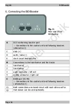
Page 38: ...t a m s e l e k t r o n i k English BiDiBooster Page 38...

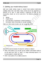
Page 39: ...t a m s e l e k t r o n i k BiDiBooster English Page 39...

Page 40: ...n Information and tips n n http www tams online de n n n Warranty and service n n Tams Elektronik GmbH n Fuhrberger Stra e 4 DE 30625 Hannover fon 49 0 511 55 60 60 fax 49 0 511 55 61 61 e mail model...

Reviews: