!
t
a
ms elektronik
LD-G-43
3.9. Connecting LEDs to the function outputs
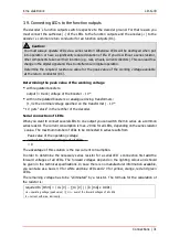
The decoder´s function outputs switch respective to the decoder ground. For that reason you
must connect the cathodes (-) of the LEDs to the function outputs and the anodes (+) to the
decoder´s common return conductor for all function outputs (RC).
Caution:
You must always operate LEDs via a series resistor! Otherwise LEDs will be destroyed when put
into operation or have a significantly reduced duration of life. If you do without a series resistor,
other components take over their function (e.g. rails, wheels, current collectors). This can lead to a
change in the digital signal and thus to interference in digital operation.
Determine the required resistance value for the peak value of the working voltage available
at the return conductor (RC).
Determining the peak value of the working voltage
with regulated boosters:
output (= track) voltage of the booster - 1 V*
with not regulated boosters or analogue driving transformers:
(1,4 x the nominal voltage specified on the transformer) - 1 V*
* 1 V gets "stuck" in the rectifier of the decoder.
Serial connection of LEDs
When you want to connect several LEDs to one output you can switch them in series via a common
series resistor. The current consumption is max. 20 mA for all LEDs, depending on the series resistor
´s value. The maximum number of LEDs to be connected in series results from
Peak value of the operating voltage
-
sum of the forward voltages of all LEDs
> 0
The advantage of this solution is the low current consumption.
In order to determine the necessary series resistor for a serial LED´s connection first add the
forward voltages of all LEDs. The forward voltages depend on the lighting colour and should
be given in the technical specifications. In case there is no manufacturer information available,
you can take as a basis 4 V for white and blue LEDs and 2 V for yellow, orange, red and green
LEDs.
The remaining voltage has to be "eliminated" by a resistor. The formula for the calculation of
the resistor is:
required R
V
[Ohm] = ( U
B
[V] – ∑ U
F
[V] ) / (I
F
[mA] x 0.001)
U
B
= operating voltage (peak value) | ∑ U
F
= sum of the forward voltages of all LEDs
I
F
= current with max. luminosity
Connections | 31
Summary of Contents for LD-G-43
Page 66: ...LD G 43 tams elektronik 66 ...
Page 67: ...tams elektronik LD G 43 67 ...


