19
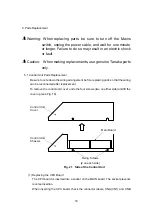
(CN2).
(When viewed from the panel, the internal battery is located on the right.)
(2) Replacing the ROM
Insert the ROM with its notch on the CN2 side, as shown in Fig. 22.
Fig. 22 The Arrangement of Parts in the Control Unit
(3) Replacing the fluorescent display
· Disconnect the cables connected to the panel on the main board from connectors
CN2 and CN3.
· Disconnect the power cable from CN1 on the fluorescent display board.
· Remove the four flat head screws from the sides of the panel and detach the panel
from the main unit.
· Remove the four screws securing the fluorescent display and disconnect the
connectors from the fluorescent display.
· Assemble the components in reverse order and check the cable connections.
Front
Main board
ROM CPU
Internal
battery
Connector code (CN1)
Connector code (CN2)
CNB (CN2)
CPU board
CNA (CN1)
ROM notch
Internal battery
soldered on
the back of the
board
(2 places)
(
−
)
(
+
)


