www.tanakapowerequipment.com
3
custsvc@tanaka-ism.com
Owner’s Manual
AST-7000
I. IMPORTANT SAFETY INSTRUCTIONS
1. Do not depress the "Start Button" while recharging the battery. This will result in damage to the
battery charger. The battery charger must be disconnected from the unit before starting.
2. Do not attempt to charge the AST-7000 battery with other than the Tanaka charger. Do not attempt to
charge other batteries with the Tanaka charger. The charger and the AST-7000 battery have specific
voltage requirements and are designed only to work together.
3. The charger is designed for standard household electrical power (AC 120V). Do not attempt to use any
other voltage.
4. Do not expose the charger to rain or snow.
5. Do not store the AST-7000 or charger where temperatures will meet or exceed 122
°
F(62
°
C).
6. Do not short circuit or in any way alter the charging system as this will result in damage to the battery
and/or the unit.
7. Do not store or operate near open flames as this may cause the battery to burst and/or release toxic
material.
II. ASSEMBLING PROCEDURES
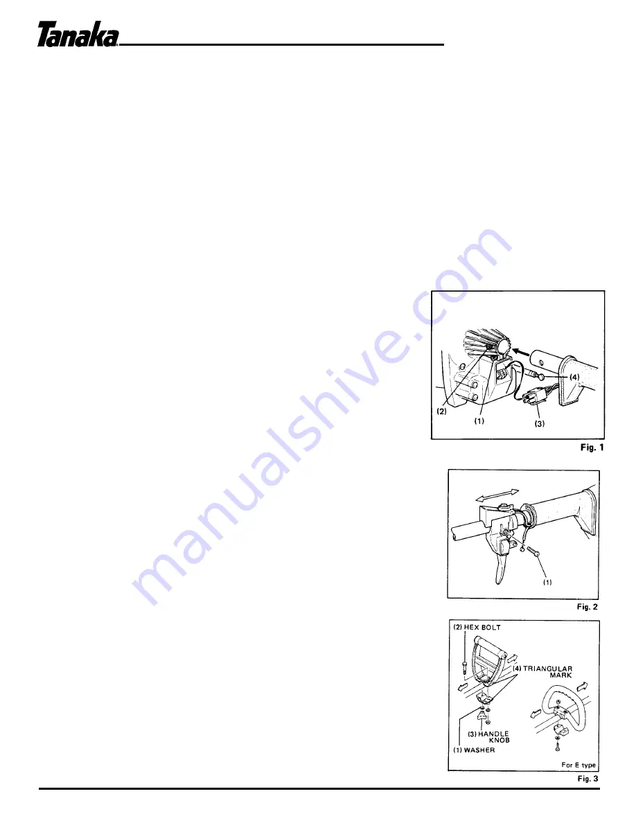
1. Drive shaft to engine (Fig. 1)
1. Loosen shaft tightening bolt (1) and location bolt (2).
2. Insert the throttle wire (4) through the hole in the bottom of
the shaft grip and connect the electrical coupling (3).
3. Push the drive shaft into the hole in the clutch case until the
shaft grip is against the clutch case.
NOTE
: If the shaft does not slide so that the grip is against the
clutch case, turn the drive shaft slightly in order to match the
splined end of the drive shaft with the splined clutch drum inside of
the clutch case.
4.
Tighten the location bolt (2) and the shaft tightening bolt (1 ).
2. Throttle control (Fig. 2)
1. Remove throttle lever screw (1) and slide the throttle lever assembly
away from the shaft grip temporarily. Connect the throttle wire in
the hole of the throttle lever.
2. Locate throttle lever in its original position by squeezing the trigger,
then slide the throttle lever assembly back against the shaft grip
then retighten the throttle lever screw (1 ).
3. Installation of handle (Fig. 3)
1. Secure the handle to the shaft as shown in Figure 3. Adjust the
handle according to your height, etc.
Note
: Keep both triangular marks of handle and handle bracket on the
same side. Tighten the mark side (Hex. bolt) first, then, handle knob.


