8
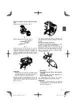
Connect stop cords. (Fig. 6)
Fig. 6
Insert the stay (5) under the nut (6) screwed onto
the outer end of the throttle wire (7) and connect the
end of the throttle wire (8) to the carburetor (9). Then
tighten the nut (6) to secure the throttle wire to the
stay (5). (Fig. 7)
9
5
7
8
6
Fig. 7
NOTE
Check that the carburetor throttle returns to the
idle position and also that it can be opened wide
by operating the throttle lever.
Cover throttle wire and stop cords together with
protective tube provided up to air cleaner cover.
(Fig. 8)
Fig. 8
Some models may come with the throttle wire and
stop cords already installed.
Installation
of
blade
guard
(Fig.
9)
The guard bracket already mounted to the drive
shaft tube.
Install the blade guard on drive shaft tube against
angle transmission (10). Tighten the guard bracket
fi
rmly so that the blade guard does not swing or
move down during operation.
10
Fig. 9
CAUTION
The
blade
guard
must
be
in
place
during
operation.
If
the
blade
guard
is
not
in
place,
there
is
a
possibility
of
serious
injury.
Blade guards are equipped with sharp line limiter.
Be careful with handling it.
NOTE
○
When attaching the guard extension to the blade
guard, the sharp line limiter must be removed
from the blade guard.
Fig. 10
○
To remove the guard extension, refer to the
drawings. Wear gloves as the extension has a
sharp line limiter, then push the two square tabs
on the guard one by one in order after removed
the screw. (Fig. 11)
Fig. 11
000Book̲TCG40EAS(P)̲̲US.indb 8
000Book̲TCG40EAS(P)̲̲US.indb 8
2009/11/27 17:15:48
2009/11/27 17:15:48


