background image

OPERATING


PROCEDURES

Fuel


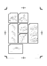
(Fig.


18)


WARNING


The trimmer is equipped with a two-stroke engine. Always run 

the engine on fuel, which is mixed with oil.


Provide good ventilation, when fueling or handling fuel.

Fuel

  Always use branded 89 octane unleaded gasoline.

  Use genuine two-cycle oil or use a mix between 25:1 to 50:1, 

please consult the oil bottle for the ratio or Tanaka dealer.

  If genuine oil is not available, use an anti-oxidant added quality 

oil expressly labeled for air-cooled 2-cycle engine use (JASO 

FC GRADE OIL or ISO EGC GRADE). Do not use BIA or TCW 

(2-stroke water-cooling type) mixed oil.

  Never use multi-grade oil (10 W/30) or waste oil. 

  Always mix fuel and oil in a separate clean container.

Always start by 

fi

 ling half the amount of fuel, which is to be used. 

Then add the whole amount of oil. Mix (shake) the fuel mixture. Add 

the remaining amount of fuel.

Mix (shake) the fuel-mix thoroughly before 

fi

 lling the fuel tank.

Fueling


WARNING

  Always shut o

  the engine before refueling.

  Slowly open the fuel tank, when 

fi

 lling  up  with  fuel,  so  that 

possible over-pressure disappears.

  Tighten the fuel cap carefully, after fueling.

  Always move the trimmer at least 3 m from the fueling area 

before starting.

Before  fueling,  clean  the  tank  cap  area  carefully,  to  ensure  that 

no dirt falls into the tank. Make sure that the fuel is well mixed by 

shaking the container, before fueling.

Starting


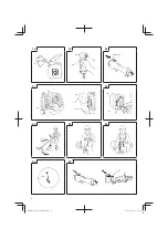
(Fig.


19,


20)

CAUTION


Before starting, make sure the cutting attachment does not 

touch anything.

1.  Set ignition switch (24) to ON position. (

Fig.


19,


20

)


*  Push priming bulb (27) several times so that fuel 

fl

 ows through 

the bulb or return pipe. (If so equipped) (

Fig.


21,


22

)

2.  With the safety trigger (25) pressed (if so equipped), pull 

throttle trigger and push throttle lock (26), then slowly release 

the throttle trigger 

fi

 rst, then the safety trigger. This will lock the 

throttle in starting position.

3.  Set choke lever to CLOSED position (28). (

Fig.


21,


22

)

4.  Pull recoil starter briskly, taking care to keep the handle in your 

grasp and not allowing it to snap back.

5.  When you hear the engine want to start, return choke lever to 

RUN position (open). Then pull recoil starter briskly again.

NOTE


If engine does not start, repeat procedures from 2 to 5.

6.  After starting engine, pull throttle trigger to release throttle lock. 

Then allow the engine about 2–3 minutes to warm up before 

subjecting it to any load.

Cutting


(Fig.


23,


24,


25,


26)

  When cutting, operate engine at over 6500 rpm. Extended time 

of use at low rpm may wear out the clutch prematurely.

  Cut grass from right to left.

  Blade thrust may occur when the spinning blade contacts a 

solid object in the critical area.


A dangerous reaction may occur causing the entire unit and 

operator to be thrust violently. This reaction is called blade 

thrust. As a result, the operator may lose control of the unit 

which may cause serious or fatal injury. Blade thrust is more 

likely to occur in areas where it is di

  cult to see the material to 

be cut.

  Wear the harness as shown in the 

fi

 gure (if so equipped). 

The blade turns counter-clockwise, therefore, be advised 

to operate the unit from right to left for e

  cient cutting. Keep 

onlookers out of working area at least 15 m.

NOTE


Press the quick release button or pull emergency release 

fl

 ap 

(If so equipped) in the event of emergency. 

(Fig.


25)


WARNING


If  cutting  attachment  should  strike  against  stones  or  other 

debris, stop the engine and make sure that the attachment 

and related parts are undamaged. When grass or vines wrap 

around attachment, stop engine and attachment and remove 

them.

Stopping


(Fig.


27)

Decrease engine speed and run at an idle for a few minutes, then 

turn o

  ignition switch (24).


WARNING


A cutting attachment can injure while it continues to spin after 

the engine is stopped or power control is released. When 

the  unit  is  turned  o

 , make sure the cutting attachment has 

stopped before the unit is set down.

MAINTENANCE

MAINTENANCE, REPLACEMENT OR REPAIR OF THE EMISSION 

CONTROL DEVICES AND SYSTEMS MAY BE PERFORMED 

BY ANY NON-ROAD ENGINE REPAIR ESTABLISHMENT OR 

INDIVIDUAL.

Carburetor


adjustment


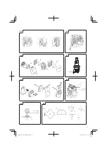
(Fig.


28)


WARNING

  The cutting attachment may be spinning during carburetor 

adjustments.

  Never start the engine without the complete clutch cover and 

tube assembled! Otherwise the clutch can come loose and 

cause personal injuries.

In the carburetor, fuel is mixed with air. When the engine is test 

run at the factory, the carburetor is basically adjusted. A further 

adjustment may be required, according to climate and altitude. The 

carburetor has one adjustment possibility:

T


=


Idle


speed


adjustment


screw.


Idle


speed


adjustment


(T)

Check that the air 

fi

 lter is clean. When the idle speed is correct, the 

cutting attachment will not rotate. If adjustment is required, close 

(clockwise) the T-screw, with the engine running, until the cutting 

attachment starts to rotate. Open (counter-clockwise) the screw 

until the cutting attachment stops. You have reached the correct 

idle  speed  when  the  engine  runs  smoothly  in  all  positions  well 

below the rpm when the cutting attachment starts to rotate.

If the cutting attachment still rotates after idle speed adjustment, 

contact your Tanaka dealer.

NOTE

  Standard Idle rpm is 2500–3000 rpm.


(TBC

-

290

/

D

/

S

/

DS,


TBC

-

340

/

D

/

S

/

DS)


The standard openings (returns) of H-screw from lightly seated 

position, is as follows. (lf so equipped)

TBC-290/D/S/DS, TBC-340/D/S/DS

H-SCREW 

1

11

G

B

D

E

G

R

P

L

H

U

C

Z

T

R

R

O

S

I

R

U

N

O

F

I

000Book̲TBC270S̲EE.indb   11

000Book̲TBC270S̲EE.indb   11

2012/07/12   15:43:07

2012/07/12   15:43:07

Summary of Contents for TVC-250PF

Page 1: ...pozorn p e t te Makineyi al t rmadan nce kullan m k lavuzunu dikkatlice okuyun Citi i cu aten ie prezentele instruc iuni nainte de utilizarea ma inii Pred uporabo naprave pozorno preberite navodila H...

Page 2: ...1 2 3 4 5 6 7 8 9 10 10 11 9 1 3 2 7 8 12 13 16 14 15 1 3 2 5 6 4 2 000Book TBC270S EE indb 2 000Book TBC270S EE indb 2 2012 07 12 15 43 02 2012 07 12 15 43 02...

Page 3: ...11 12 13 14 15 16 17 17 18 18 18 19 21 22 20 23 17 cm 17 cm CH 100 19 19 3 000Book TBC270S EE indb 3 000Book TBC270S EE indb 3 2012 07 12 15 43 03 2012 07 12 15 43 03...

Page 4: ...18 19 20 21 22 23 24 25 26 27 24 25 28 28 27 15 m 27 26 25 26 24 4 000Book TBC270S EE indb 4 000Book TBC270S EE indb 4 2012 07 12 15 43 03 2012 07 12 15 43 03...

Page 5: ...28 30 29 31 32 33 34 35 29 29 29 0 6 mm 30 31 R1 1 5 mm 1 9 2 2 mm 5 000Book TBC270S EE indb 5 000Book TBC270S EE indb 5 2012 07 12 15 43 04 2012 07 12 15 43 04...

Page 6: ...yone approaches you stop the engine and cutting attachment immediately Indicate handle location Do not attach handle above this point Be careful of thrown objects WARNING Read the Operator s Manual an...

Page 7: ...tween pictures and your unit Use the instructions that apply to your unit 1 Fuel cap 2 Throttle trigger 3 Starter handle 4 Blade guard 5 Cutting attachment 6 Drive shaft tube 7 Handle bar 8 Suspension...

Page 8: ...aces etc WARNING Fuel is easy to ignite or get explosion or inhale fumes so that pay special attention when handling or filling fuel Cutting safety Do not cut any material other than grass and brush I...

Page 9: ...evel LwA dB A 116 112 116 Vibration level m s2 ISO7916 Front handle Rear handle Left handle Right handle 2 6 4 1 3 5 5 6 2 4 2 5 1 9 2 0 5 4 5 2 3 7 7 1 1 8 2 1 2 5 2 9 2 6 3 3 3 7 6 3 1 6 2 7 2 0 5 0...

Page 10: ...guard Fig 11 12 13 NOTE The guard bracket may come already mounted to the gear case on some models Install the blade guard and the bracket spacers 17 If so equipped on drive shaft tube against angle t...

Page 11: ...on may occur causing the entire unit and operator to be thrust violently This reaction is called blade thrust As a result the operator may lose control of the unit which may cause serious or fatal inj...

Page 12: ...gine is air cooled and air must circulate freely around engine and over cooling fins on cylinder head to prevent overheating Every 100 operating hours or once a year more often if conditions require c...

Page 13: ...s sich jemand n hert den Motor und das Zubeh r sofort ausschalten Bezeichnet den Gri stangenplatz Gri stange nicht oberhalb dieses Punktes anbringen Auf hochgeschleuderte Gegenst nde achten WARNUNG Le...

Page 14: ...gilt k nnen die Abbildungen gegebenenfalls von Ihrem Ger t abweichen Verwenden Sie die f r Ihr Ger t geltenden Anweisungen 1 Benzintank 2 Gashebel 3 Startgri 4 Messerschutz 5 Schneid Vorsatzger t 6 An...

Page 15: ...zulassen Mit gef lltem Tank ist das Ger t so zu lagern dass kein Kraftsto ausl uft Ger t und Kraftsto an einem Ort lagern wo Kraftsto d mpfe nicht mit Funken oder o enen Flammen von Wassererhitzern El...

Page 16: ...67 Trockengewicht kg 5 4 5 56 D 5 6 5 76 5 5 5 66 D 5 7 5 86 5 0 D 5 8 5 0 DS 5 7 SF 5 2 SFS 5 4 PFDS 6 1 PFS 5 2 Schalldruckpegel LpA dB A EN27917 95 0 D 95 5 94 5 92 5 D 91 8 97 5 DS 98 3 SF 97 5 9...

Page 17: ...ng Den mitgelieferten Schutzschlauch bis zum Luftfilterdeckel ber Gaszug und Stoppkabel ziehen Abb 10 Anbringung des Messerschutzes Abb 11 12 13 HINWEIS Bei einigen Modellen wird das Getriebegeh use b...

Page 18: ...pe 27 mehrmals bet tigen damit Kraftsto durch die Pumpe oder das R cklaufrohr flie t Falls vorhanden Abb 21 22 2 Bei gedr cktem Sicherheitshebel 25 falls vorhanden den Gashebel anziehen und dann den S...

Page 19: ...mit Vergasereinstellungen nicht vertraut sind wenden Sie sich bitte an Ihren Tanaka H ndler WARNUNG Im Leerlauf darf sich das Schneidwerkzeug auf keinen Fall mitdrehen Luftfilter Abb 29 Den Luftfilter...

Page 20: ...on f hren Messer aussondern die verbogen verzogen rissig gebrochen oder in anderer Weise besch digt sind HINWEIS Beim Sch rfen der Klinge ist es wichtig dass die urspr ngliche Radiusform an der Zahnba...

Page 21: ...E 15 21 G B D E G R P L H U C Z T R R O S I R U N O F I 000Book TBC270S EE indb 21 000Book TBC270S EE indb 21 2012 07 12 15 43 10 2012 07 12 15 43 10...

Page 22: ...15 m 23 24 25 26 27 28 22 000Book TBC270S EE indb 22 000Book TBC270S EE indb 22 2012 07 12 15 43 10 2012 07 12 15 43 10...

Page 23: ...11 11 11 9 9 9 12 12 8 8 8 14 14 14 14 8 13 13 13 13 1 3 1 1 1 1 3 3 4 2 4 4 5 15 4 6 16 7 8 8 11 11 9 9 12 12 12 14 3 13 1 2 4 K 1 2 3 4 5 6 7 8 9 10 11 12 13 14 15 16 17 18 23 G B D E G R P L H U C...

Page 24: ...HAVS 3 Tanaka 24 000Book TBC270S EE indb 24 000Book TBC270S EE indb 24 2012 07 12 15 43 12 2012 07 12 15 43 12...

Page 25: ...6 1 PFS 5 2 LpA dB A EN27917 95 0 D 95 5 94 5 92 5 D 91 8 97 5 DS 98 3 SF 97 5 92 0 LwA dB A 116 112 116 m s2 ISO7916 2 6 4 1 3 5 5 6 2 4 2 5 1 9 2 0 5 4 5 2 3 7 7 1 1 8 2 1 2 5 2 9 2 6 3 3 3 7 6 3 1...

Page 26: ...11 9 10 5 6 8 9 10 7 TBC 270PFS PFDS SFS 6 8 12 13 14 13 15 16 10 11 12 13 17 13 Tanaka CH 100 CH 300 18 19 14 15 16 20 Allen 21 22 23 26 000Book TBC270S EE indb 26 000Book TBC270S EE indb 26 2012 07...

Page 27: ...FC GRADE OIL ISO EGC GRADE BIA TCW 10 W 30 3 19 20 1 24 ON 19 20 27 21 22 2 25 26 3 CLOSED 28 21 22 4 5 RUN 2 5 6 2 3 23 24 25 26 6500 15 25 27 G B D E G R P L H U C Z T R R O S I R U N O F I 000Book...

Page 28: ...T T Tanaka 2500 3000 TBC 290 D S DS TBC 340 D S DS TBC 290 D S DS TBC 340 D S DS 1 90 Tanaka 29 29 30 31 0 6 100 28 000Book TBC270S EE indb 28 000Book TBC270S EE indb 28 2012 07 12 15 43 12 2012 07 12...

Page 29: ...100 33 100 34 50 3 4 35 Tanaka 25 4 31 4 30 Tanaka 0 6 3 4 29 G B D E G R P L H U C Z T R R O S I R U N O F I 000Book TBC270S EE indb 29 000Book TBC270S EE indb 29 2012 07 12 15 43 13 2012 07 12 15 43...

Page 30: ...miast wy czy silnik zatrzymuj c ostrze Wskazuje lokalizacj uchwytu Nie nale y zaczepia uchwytu powy ej tego punktu Nale y uwa a na odrzucane przedmioty OSTRZE ENIE Nale y przeczyta instrukcje obs ugi...

Page 31: ...iadanego przez u ytkownika Nale y stosowa si do zalece dotycz cych posiadanego urz dzenia 1 Korek paliwa 2 Wyzwalacz przepustnicy 3 Uchwyt startera 4 Os ona ostrza 5 Akcesorium tn ce 6 Obudowa wa u na...

Page 32: ...s b aby paliwo nie wyciek o Urz dzenie maszyn i paliwo przechowywa w takich miejscach w kt rych opary paliwa nie dochodz do iskier i otwartych p omieni grzejnik w wody silnik w elektrycznych lub wy cz...

Page 33: ...a sucho kg 5 4 5 56 D 5 6 5 76 5 5 5 66 D 5 7 5 86 5 0 D 5 8 5 0 DS 5 7 SF 5 2 SFS 5 4 PFDS 6 1 PFS 5 2 Poziom ci nienia d wi ku LpA dB A EN27917 95 0 D 95 5 94 5 92 5 D 91 8 97 5 DS 98 3 SF 97 5 92 0...

Page 34: ...icy i linki ograniczaj ce za pomoc dostarczonej rurki zabezpieczaj cej a do pokrywy filtra powietrza Rys 10 Zak adanie os ony ostrza Rys 11 12 13 UWAGA W przypadku niekt rych modeli wspornik os ony je...

Page 35: ...przycisk spustowy przepustnicy a nast pnie przycisk zabezpieczaj cy Spowoduje to automatyczne zablokowanie przepustnicy w pozycji rozruchu 3 Ustawi d wigni w po o eniu CLOSED zamkni te 28 Rys 21 22 4...

Page 36: ...na dok adnie wyczy ci Z tego wzgl du nale y okresowo wymienia go na nowy filtr Uszkodzony filtr nale y wymieni natychmiast Filtr paliwa Rys 30 Spu ci ca o paliwa ze zbiornika i wyci gn link filtra pa...

Page 37: ...e jest uszkodzona Sprawdzi czy os ona ostrza nie nosi adnych lad w uszkodze lub p kni Je eli os ona jest uszkodzona lub p kni ta nale y wymieni j na now Sprawdzi czy akcesorium tn ce jest w a ciwie wy...

Page 38: ...motort s a v g szerelv nyt A kar hely t mutatja Enn l magasabbra ne helyezze a kart gyeljen a sz ll repeszekre FIGYELMEZTET S Olvassa el a kezel i tmutat t s tartsa be az abban foglalt figyelmeztet s...

Page 39: ...k zik nyvben br zolt k pek elt rhetnek az n egys g t l Csak az n egys g re vonatkoz utas t sokat vegye figyelembe 1 Tanksapka 2 G zadagol kar 3 Ind t kar 4 Pengev d 5 V g szerelv ny 6 Kard ntengely cs...

Page 40: ...eni Amennyiben maradt zemanyag a tankban gy t rolja hogy az ne sziv rogjon Az egys get g pet s zemanyagot olyan helyen t rolja ahol az zemanyagg zzel szikra s ny lt l ng nem rintkezhet mely p ld ul bo...

Page 41: ...86 5 0 D 5 8 5 0 DS 5 7 SF 5 2 SFS 5 4 PFDS 6 1 PFS 5 2 Hangnyom s szint LpA dB A EN27917 95 0 D 95 5 94 5 92 5 D 91 8 97 5 DS 98 3 SF 97 5 92 0 Hanger szintje LwA dB A 116 112 116 Vibr ci szint m s2...

Page 42: ...modellekn l a v d keret gy rilag fel van szerelve a h zra Szerelje fel a pengev d t s a keret t vtart it 17 ha van a kard ntengely cs re a v lt n l H zza meg er sen a v d keretet hogy a pengev d ne m...

Page 43: ...id el tti elpok s hoz vezethet A f vet jobb l balra v gja Pengel k s k vetkezhet be ha a p rg penge hozz r egy t m r t rgyhoz a kritikus r szen Ilyenkor vesz lyes helyzet llhat el a teljes egys get s...

Page 44: ...sz ks ges ll tsa be jra A megfelel h zag 0 6 mm A gyerty kat 100 ra m k d s ut n cser lni kell vagy kor bban ha az elektr d k nagyon rozsd sak MEGJEGYZ S Bizonyos telep l seken a helyi t rv nyek megk...

Page 45: ...h zagot ll tsa be 0 6 mm re vagy cser lje a gyerty t Tiszt tsa meg a motorblokk h t bord it s ellen rizze hogy az ind t egys g leveg be ml je nincs e elz r dva Ellen rizze hogy a hajt m 3 4 r szig fel...

Page 46: ...nem li p ibli ovat na m n ne 15 m Pokud se k v m n kdo p ibl ihned vypn te motor a sekac agreg t Signalizace polohy rukojeti Rukoje nep ipojovat nad t mto bodem Pozor na odletuj c p edm ty VAROV N t...

Page 47: ...ozd ly mezi obr zky a va m za zen m Pou ijte pokyny kter plat pro va e za zen 1 V ko palivov n dr e 2 Ovlada p vodu paliva 3 Startovac p ka 4 Kryt no e 5 Sekac agreg t 6 Man eta h dele 7 Madlo 8 Z v s...

Page 48: ...a nebyly v kontaktu s jiskrou nebo otev en m plamenem pozor na bojlery elektromotory sp na e kotle atd VAROV N P i manipulaci s palivem dbejte mimo dn opatrnosti proto e je snadno vzn titeln explozivn...

Page 49: ...akustick ho v konu LwA dB A 116 112 116 Hladina vibrac m s2 ISO7916 P edn rukoje Zadn rukoje Lev rukoje Prav rukoje 2 6 4 1 3 5 5 6 2 4 2 5 1 9 2 0 5 4 5 2 3 7 7 1 1 8 2 1 2 5 2 9 2 6 3 3 3 7 6 3 1 6...

Page 50: ...dru p evodovky Instalujte kryt no e a vlo ky dr ku 17 pokud existuj na man etu h dele proti ku elov mu p evodu Ut hn te dr k krytu pevn tak aby se kryt no e nek val ani b hem provozu nesj d l Instaluj...

Page 51: ...t Popruh noste tak jak je zn zorn no na obr zku pokud existuje N se to proti sm ru hodinov ch ru i ek proto abyste dos hli efektivn ho sek n pracujte zprava doleva V echny ostatn osoby se mus vzd lit...

Page 52: ...bo ast ji pokud to vy aduj podm nky odstra te z eber a venkovn ch povrch motoru sady prachu p ny a oleje kter mohou zhor ovat chlazen POZN MKA Motor nespou t jte pokud jsou clona motoru nebo kryt tlum...

Page 53: ...erhangi bir ki i yakla rsa motoru ve kesme donan m n derhal durdurun Kolun yerini g sterir Kolu bu noktan n zerine takmay n Savrulan cisimlere dikkat edin UYARI Kullan m K lavuzunu okuyun ve t m uyar...

Page 54: ...in resimler ile cihaz n z aras nda baz farklar olabilir Cihaz n z i in ge erli olan talimatlar kullan n 1 Yak t kapa 2 Gaz teti i 3 Mar d zene i kolu 4 B ak mahfazas 5 Kesme donan m 6 Tahrik mili boru...

Page 55: ...i ve yak t ofbenlerden elektrikli motorlardan veya alterlerden f r nlardan vb kan alev veya k v lc mlar n yak t buharlar na ula amayaca bir yerde saklay n UYARI Yak t kolayca alev alabilir patlayabili...

Page 56: ...97 5 92 0 Ses g c seviyesi LwA dB A 116 112 116 Titre im seviyesi m s2 ISO7916 n kabza Arka kabza Sol kabza Sa kabza 2 6 4 1 3 5 5 6 2 4 2 5 1 9 2 0 5 4 5 2 3 7 7 1 1 8 2 1 2 5 2 9 2 6 3 3 3 7 6 3 1 6...

Page 57: ...11 12 13 NOT Baz modellerde mahfaza deste i di li kutusuna monte edilmi olarak gelebilir B ak mahfazas n ve bu donan ma sahipse destek pullar n 17 tahrik mili borusuna a transmisyonuna kar monte edin...

Page 58: ...m kavraman n zaman ndan nce a nmas na sebep olabilir imleri sa dan sola do ru kesin H zla d nen b ak kritik alanda kat bir cisimle temas etti inde b ak geri itilebilir B t n nitenin ve operat r n idd...

Page 59: ...in diren li buji kullan lmas n gerektirmektedir Makinenizde diren li buji varsa eskiyen bujiyi yine ayn tipte buji ile de i tirin Susturucu ekil 32 Her 100 saatlik al madan sonra susturucuyu kar n ve...

Page 60: ...deki so utma kanatlar n temizleyin ve mar motoruna hava giri inin t kal olup olmad n kontrol edin Konik di linin 3 4 e kadar gresle dolu olup olmad n kontrol edin Hava filtresinin temizlenmesi Ayl k b...

Page 61: ...tivul de t iere Indic pozi ia m nerului Nu ata a i m nerul deasupra acestui punct Fi i atent la obiectele instabile AVERTISMENT Citi i Manualul operatorului i respecta i toate aten ion rile i instruc...

Page 62: ...iliza i instruc iunile care sunt aplicabile aparatului dumneavoastr 1 Bu onul rezervorului de carburant 2 Maneta de accelera ie 3 Demaror 4 Ap r toare 5 Dispozitiv de t iere 6 Tij de transmisie 7 M ne...

Page 63: ...a a fel nc t carburantul s nu curg Depozita i dispozitivul aparatul i carburantul n locuri n care vaporii de carburant nu pot intra n contact cu sc ntei sau fl c ri deschise de la dispozitive de nc lz...

Page 64: ...LpA dB A EN27917 95 0 D 95 5 94 5 92 5 D 91 8 97 5 DS 98 3 SF 97 5 92 0 Nivel putere sunet LwA dB A 116 112 116 Nivel vibra ii m s2 ISO7916 M ner frontal M ner lateral M ner dreapta M ner st nga 2 6...

Page 65: ...12 13 NOT La anumite modele suportul ap r torii poate fi deja montat pe cutia de angrenare Monta i ap r toarea i distan ierele de suport 17 dac este echipat pe tija de transmisie l ng angrenajul de t...

Page 66: ...dispozitivul de blocare Apoi permite i motorului s mearg n gol timp de 2 3 minute pentru a se nc lzi nainte de a l supune la orice sarcin Cosire Fig 23 24 25 26 n timpul cositului motorul func ioneaz...

Page 67: ...ensiune redus demareaz greu sau func ioneaz slab la viteza de rota ie n gol verifica i n primul r nd bujia Dac bujia este murdar cur a i o i verifica i golul electrodului Regla i din nou dac este nece...

Page 68: ...li ele i uruburile s fie str nse suficient de tare ntre inere s pt m nal Verifica i starterul n special coarda i arcul de ntoarcere Cur a i exteriorul bujiei Demonta i o i verifica i distan a dintre e...

Page 69: ...orkoli pristopi takoj ustavite motor in priklju ek za rezanje Ozna ite mesto za ro aj Ne priklju ujte ro aj nad to to ko Bodite pozorni na vr ene predmete OPOZORILO Preberite Priro nik za upravljalca...

Page 70: ...va o enoto Uporabite navodila ki se nana ajo na va o enoto 1 Pokrov posode za gorivo 2 Spro ilec du ilke 3 Ro ica zaganja a 4 Varovalo rezila 5 Priklju ek za rezanje 6 Cev pogonske grede 7 Krmilo 8 O...

Page 71: ...i iskrenja in odprtega ognja iz vodnih grelnikov elektri nih motorjev stikal pe i itd OPOZORILO Gorivo je hitro vnetljivo in eksplozivno ter kodljivo za vdihavanje zato delajte in nalivajte gorivo izr...

Page 72: ...3 SF 97 5 92 0 Zvo na mo LwA dB A 116 112 116 Raven vibracije m s2 ISO7916 Ro aj spredaj Ro aj zadaj Ro aj levi Ro aj desni 2 6 4 1 3 5 5 6 2 4 2 5 1 9 2 0 5 4 5 2 3 7 7 1 1 8 2 1 2 5 2 9 2 6 3 3 3 7...

Page 73: ...ena na ohi ju opreme Namestite varovalo za rezilo in vmesnike konzole 17 e je v opremi na cev pogonske grede proti prenosu kota Trdno zategnite konzolo varovala tako da se varovalo za rezilo ne premi...

Page 74: ...proti levi strani Rezilo se lahko prebode e rezilo ki se obra a pride v kontakt s trdnim predmetom v kriti nem obmo ju Lahko pride do nevarne reakcije ki lahko povzro i nasilen sunek celotne enote in...

Page 75: ...ko zamenjajte s sve ko enake vrte Du ilec Sl 32 Odstranite du ilec in po istite kakr en koli prese ni ogljik iz izpu nega izhoda ali vhoda v du ilec vsakih 100 ur dela Cilinder Hlajenje motorja Sl 33...

Page 76: ...prema kota napolnjena z mastjo do 3 4 O istite zra ni filter Mese no vzdr evanje Izperite posodo za gorivo s bencinom O istite zunanjo povr ino uplinja a in obmo je okoli uplinja a O istite ventilator...

Page 77: ...Brain 15 15 78 79 81 82 83 84 77 G B D E G R P L H U C Z T R R O S I R U N O F I 000Book TBC270S EE indb 77 000Book TBC270S EE indb 77 2012 07 12 15 44 19 2012 07 12 15 44 19...

Page 78: ...6 6 6 7 7 7 7 2 2 2 2 11 11 11 9 9 9 12 12 8 8 8 14 14 14 14 8 13 13 13 13 1 3 1 1 1 1 3 3 4 2 4 4 5 15 4 6 16 7 8 8 11 11 9 9 12 12 12 14 3 13 1 2 4 1 2 3 4 5 6 7 8 9 10 11 12 13 14 15 16 17 Combi 18...

Page 79: ...3 15 Tanaka 79 G B D E G R P L H U C Z T R R O S I R U N O F I 000Book TBC270S EE indb 79 000Book TBC270S EE indb 79 2012 07 12 15 44 21 2012 07 12 15 44 21...

Page 80: ...Tanaka 80 000Book TBC270S EE indb 80 000Book TBC270S EE indb 80 2012 07 12 15 44 21 2012 07 12 15 44 21...

Page 81: ...1 PFS 5 2 L EN27917 95 0 D 95 5 94 5 92 5 D 91 8 97 5 DS 98 3 SF 97 5 92 0 LwA A 116 112 116 2 ISO7916 2 6 4 1 3 5 5 6 2 4 2 5 1 9 2 0 5 4 5 2 3 7 7 1 1 8 2 1 2 5 2 9 2 6 3 3 3 7 6 3 1 6 2 7 2 0 5 0...

Page 82: ...8 4 11 9 10 5 6 8 9 10 7 TBC 270PFS PFDS SFS 6 8 12 13 14 13 15 16 10 11 12 13 17 13 Tanaka CH 100 CH 300 18 19 14 15 16 20 21 22 23 82 000Book TBC270S EE indb 82 000Book TBC270S EE indb 82 2012 07 12...

Page 83: ...FC GRADE OIL ISO EGC GRADE BIA TCW 10 W 30 3 19 20 1 24 ON 19 20 27 21 22 2 25 26 3 CLOSED 28 21 22 4 5 RUN 2 5 6 2 3 23 24 25 26 6500 15 25 83 G B D E G R P L H U C Z T R R O S I R U N O F I 000Book...

Page 84: ...T Tanaka 2500 3000 TBC 290 D S DS TBC 340 D S DS TBC 290 D S DS TBC 340 D S DS H 1 90 Tanaka 29 29 30 31 0 6 100 84 000Book TBC270S EE indb 84 000Book TBC270S EE indb 84 2012 07 12 15 44 21 2012 07 12...

Page 85: ...00 33 100 34 50 3 4 35 Tanaka 25 4 1 31 4 30 Tanaka 0 6 3 4 85 G B D E G R P L H U C Z T R R O S I R U N O F I 000Book TBC270S EE indb 85 000Book TBC270S EE indb 85 2012 07 12 15 44 21 2012 07 12 15 4...

Page 86: ...86 000Book TBC270S EE indb 86 000Book TBC270S EE indb 86 2012 07 12 15 44 22 2012 07 12 15 44 22...

Page 87: ...87 000Book TBC270S EE indb 87 000Book TBC270S EE indb 87 2012 07 12 15 44 22 2012 07 12 15 44 22...

Page 88: ...n conformitate cu directivele Consiliului 98 37 CE 2004 108 CE i 2000 14 CE Acest produs se conformeaz de asemenea cerin elor de baz ale 2006 42 CE care urmeaz s fie aplicate ncep nd cu 29 decembrie...

Reviews: