background image

                                                                                                       TX7331 Intelligent Graphic Repeater Panel  


        Installation & Operation Manual  

                                                                                                                               4050100365-Rev1.1-1117                                                                      


    TANDA UK  


Specifications are subject to change without prior notice 


2 Installation   


2.1 Installation Preparation 

This  Intelligent  Graphic  Repeater  Panel  must  be  installed,  commissioned  and  maintained  by  a 
qualified or factory trained service personnel. The installation must be installed in compliance with all 
local codes having a jurisdiction in your area or BS 5839 Part 1 and EN54. 

Warning: 

The electronic components inside the panel are vulnerable to damage by electrostatic 

discharges. It is recommended to wear a wrist strap designed to prevent the build-up of static 

charges within the body, before handling any electronic circuit board. 

2.2 Installation and Wiring 


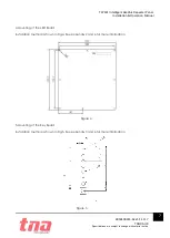
1

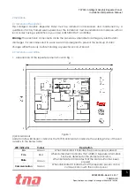
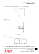
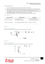
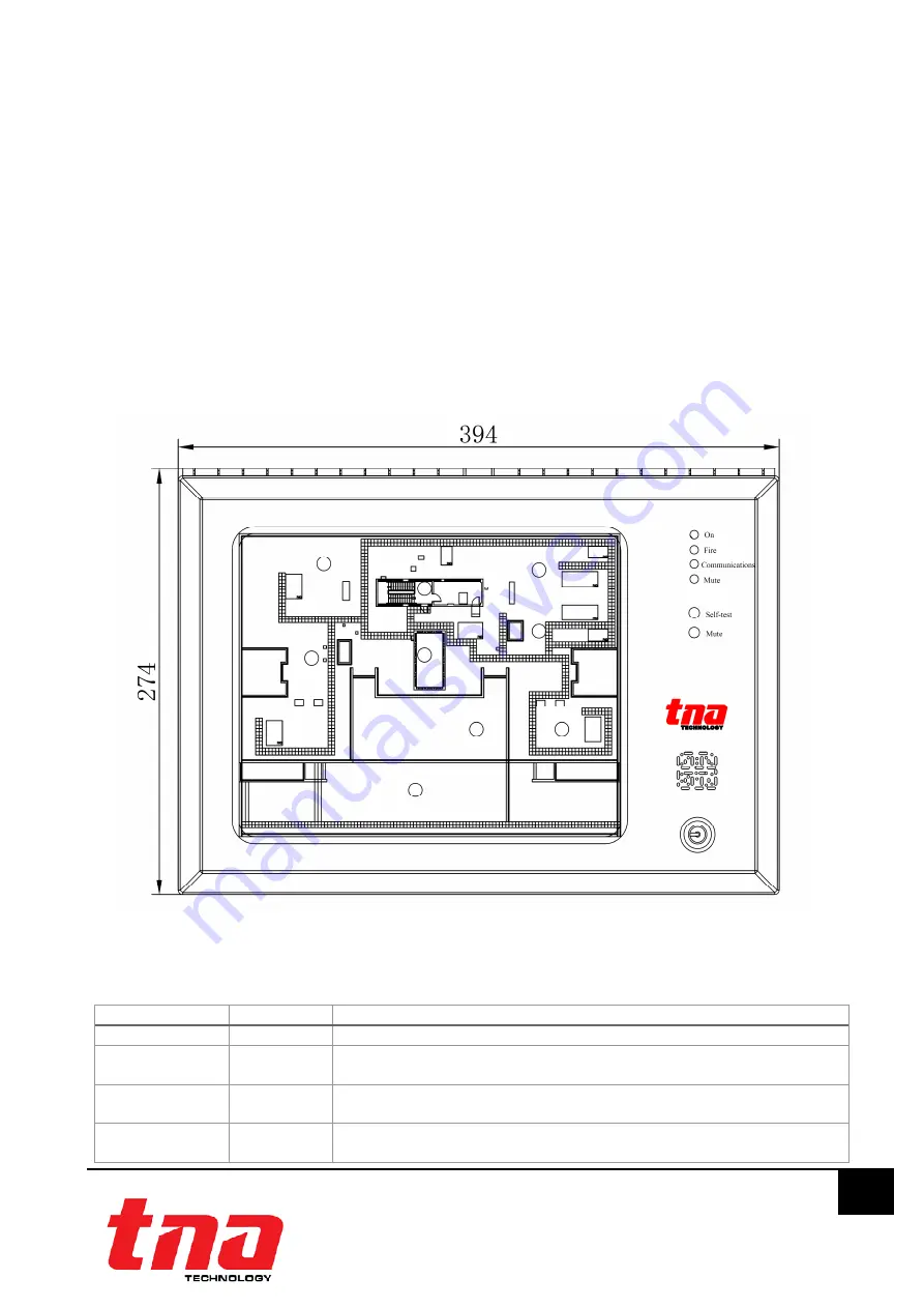
Appearance of the repeater panel is shown in Fig. 1.


(1)LED Indicators 
Aside from the LED Board

´

s Indicator, the TX7331 LED indicator indicate the working status of the unit 

as refers to the below table. 


LED Indicator 

Colour 

Description 

On


Green 

When illuminated it indicates the power supply is present 

Fire


Red 

When illuminated it indicates that a FIRE or Supervise information 

has been detected in the protected location 

Mute


Green 

When illuminated it indicates that the MUte button has been 

pressed  

Communication 

Green 

When illuminated it indicates that the repeater panel is online 

communication with the control panel 

Figure 1 

Summary of Contents for TX7331

Page 1: ...TX7331 Intelligent Graphic Repeater Panel Installation and Operation Manual TANDA UK Technology Copyright 2015 All right reserved...

Page 2: ...ing the Intelligent Graphic Repeater Panel to ensure proper and safe operation of the system European Union directive 2012 19 EU WEEE directive Products marked with this symbol cannot be disposed of a...

Page 3: ...2 2 Installation and Wiring 5 3 Operation 9 3 1 Preparation 9 3 2 Repeater Addressing 9 3 3 LED Panel Operations 10 4 General Maintenance 11 5 Troubleshooting 11 Appendix 1 11 Installation of the Mai...

Page 4: ...ent modern building designs The unit is compatible to the TX7004 Analogue Intelligent Fire Alarm Control Panel produced by single manufacture T A to avoid addressable communication compatibility probl...

Page 5: ...ded to wear a wrist strap designed to prevent the build up of static charges within the body before handling any electronic circuit board 2 2 Installation and Wiring 1 Appearance of the repeater panel...

Page 6: ...on of Keys MUTE This button mutes the buzzer of the repeater panel Pressing the mute button will stop the internal panel buzzer Self test In standby state pressing this key the repeater panel will sta...

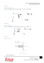
Page 7: ...A UK Specifications are subject to change without prior notice 7 4 Mounting of the LED Board Installation method is shown in Fig 4 See Appendix 2 and 6 for more information 5 Mounting of the Key Board...

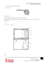
Page 8: ...6 Mounting of the Buzzer Installation method is shown in Fig 6 See Appendix 4 and 6 for more information 7 Mounting of the LED Installation method is shown in Fig 7 See Appendix 5and 6 for more inform...

Page 9: ...he site situation and environmental requirements Program a unique address number for each device according to the project layout before placing from the Terminal Base Warning Disconnect the loop conne...

Page 10: ...e Supervise information 1 Configuration Preparation According to the figure 13 configuration Switched on the 24VDC power to the Repeater Panel s Main board and the USB connect with computer 2 Configur...

Page 11: ...arranty 4 Notify again proper personnel after conducting the maintenance and make sure to enable the Intelligent Graphic Repeater Panel and confirm if up and running 5 Perform the maintenance on semi...

Page 12: ...subject to change without prior notice 12 Appendix 3 Limitation of the Key Board As shown in the figure below is Key Board with the door weld nut Connection Appendix 4 Limitation of the Buzzer As sho...

Page 13: ...bject to change without prior notice 13 2 Nylon sleeve of light emitting diode 3 front panel Assembly steps Please put lights in accordance with the directions in the hole According with the B indicat...

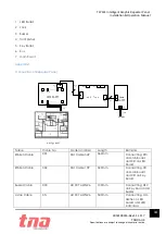
Page 14: ...ain Board Appendix7 Connection of Repeater Panel Name Cable No Model and Size Length Remarks Ribbon Cable X01 Flat Cable 34P 360mm Connecting XT3 on Main Board and XS1on LED board Ribbon Cable X02 Fla...

Page 15: ...continuously according to recommendations from manufacturers and relative nation codes and laws Take specific maintenance measures on the basis of different environments These Intelligent Graphic Repe...

Reviews: