Introduction to the Basic Encoder
Instruction Manual: evolution 5000 E5710 and E5720 Encoder
Page 1-17
ST.TM.E10074.1
1.4.4
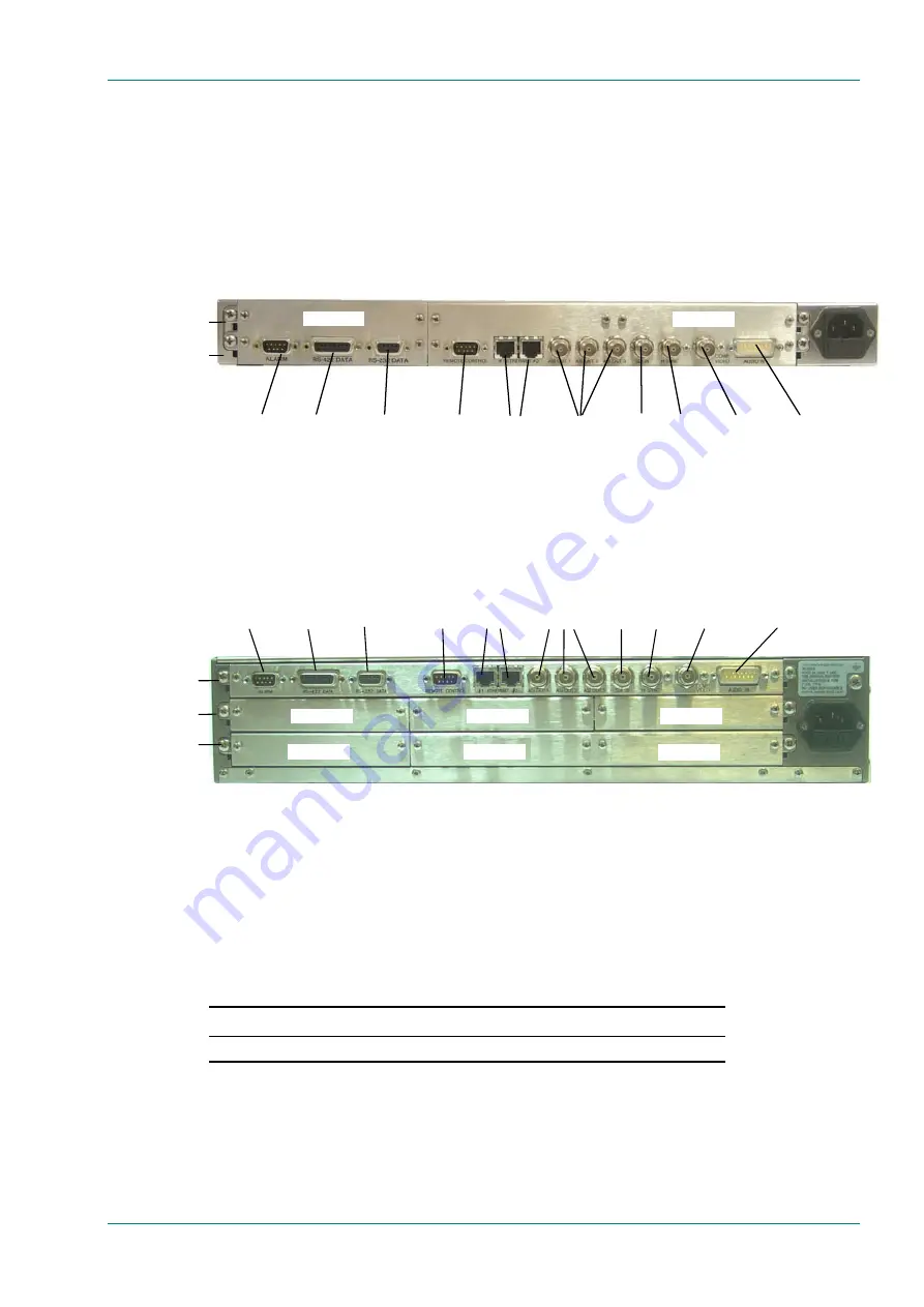
Rear Panel Description
Introduction
The Encoder provides connectors at the rear panel. All, except the power
connector, are physically located on the separate modules which comprise
the Encoder.
1U Chassis
Figure 1.10: E5710 (1U) Rear Panel Component Parts and Connectors
2U Chassis
Figure 1.11: E5720 (2U) Rear Panel Component Parts and Connectors
1.4.5
Boards in the Basic Encoder
The basic Encoder contains one board mounted horizontally in the
enclosure (see Table 1.8). Option modules can be fitted in the remaining
slots; two in the 1U version and up to six in the 2U (see Figure 1.10,
Figure 1.11 and Chapter 3, Options and Upgrades).
Table 1.8: Boards in the Basic Encoder
Model Number
Card
E5710 / E5720
S11171 Encoder Base Board
Access to the modules or the Base Board is not required for normal
operation and may invalidate the warranty.
Option Slot 1
Option Slot 2
Option Slot 3
Option Slot 4
Option Slot 5
Option Slot 6
Option Slots 1-3
Audio In and
Audio
Reference Out
H Sync
Composite
Video
ASI
Outputs
RS-232
Data
RS-422
Data
Alarm
RS-232/
RS-485
Control
SDI In
Ethernet
Option Slots 4-6
Base Board
Audio In and
Audio
Reference Out
H Sync Composite
Video
ASI Outputs
Ethernet
RS-232
Data
RS-422
Data
Alarm
RS-232/
RS-485
Control
SDI In
Option Slot 1
Option Slot 2
Base Board
Option Slots 1-2


