Installing the Equipment
Page 2-16
Instruction Manual: evolution 5000 E5710 and E5720 Encoder
ST.TM.E10074.1
2.6.2
Powering Up
To power up the Encoder:
1.
Turn on the local power supply. The Encoder executes a series of
power-up initialisation and self-test routines.
2.
Confirm that the green Power LED is lit and that the red Alarm LED is
unlit.
3.
Ensure that the Stand-by switch is set to On (see Chapter 1,
Introduction, Figure 1.8).
After the boot period the Encoder start-up screen is displayed.
NOTE…
The fans on the Encoder can be temperature controlled so may not be on if the ambient temperature is
low. Refer to Annex B, Technical Specification, Table B.19 for more information.
2.6.3
Powering Down
To power down the Encoder remove the power supply connection at the
rear of the unit.
2.7
Setting up the Encoder for Reflex Operation
2.7.1
Overview
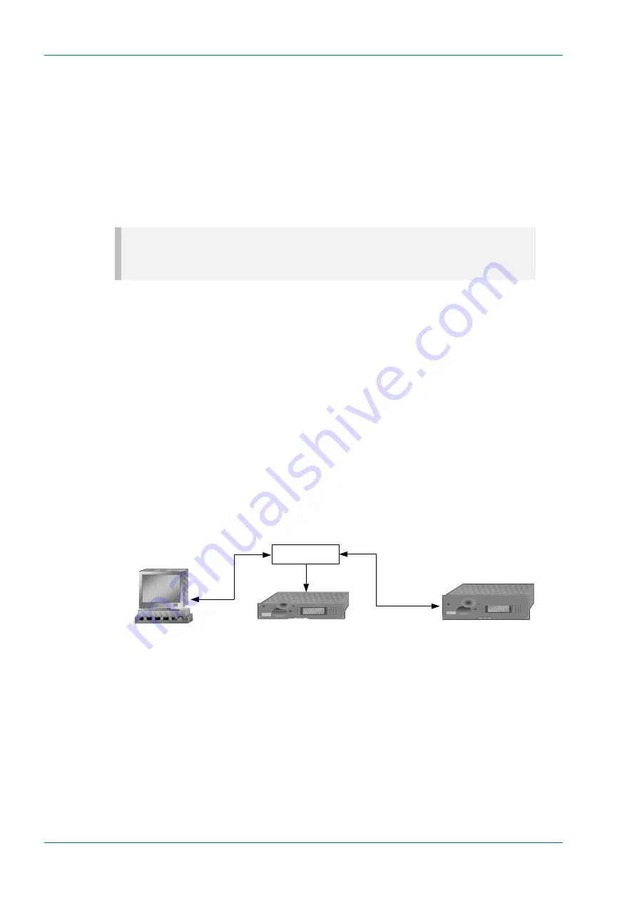
To allow the Encoder to operate in Reflex mode, it must communicate with
the Multiplexer on a frame by frame basis. These communications make
use of the Ethernet connection on the Encoder Base Board. Messages carry
performance information from the Encoder to the Multiplexer and bit-rate
instructions from the Multiplexer to the Encoder.
Figure 2.6: Setting Up the Encoder for Reflex Operation
To allow the system to operate correctly, the port number on the Encoder
must be set to match that configured for Reflex in the Multiplexer. In a
multiple head-end system, each Multiplexer (and its spare, if a redundant
configuration is employed) will be configured to use a different Reflex port
number.
Further, it is necessary for the Encoder to be resident on the same IP
subnet as the Multiplexer (see Section 2.8, Setting the Encoder IP
Address).
TANDBERG
1 2 3
4 5 6
7 8 9
0 *
±
evolution 5000
Encoder
TANDBERG
1 2 3
4 5 6
7 8 9
0 *
±
evolution 5000
Multiplexer
Ethernet
Telnet session
Ethernet Hub
Encoder performance
®
¬
Bit-rate instructions


