Technical Description of TANDBERG MCU with software version D3
D12925 Rev. 03
22
4.2 Aggregation Standards
ISDN Aggregation
H.221
Frame Structure from 64 (56
*
) kbps to 128 kbps
ISO 13871
BONDING, Mode 1 from 64 (56
*
) kbps to 2 Mbps
H0
One
384
kbps
channel
4.2.1 BONDING
•
ISO 13871, BONDING Mode 1 for bit rates from 56 kbps up to 2 Mbps (1 to 30 channels).
•
The maximum relative delay difference between B-channels is 0.5 second (i.e. to compensate
for different routing of channels).
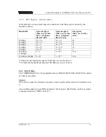
The following are the standard bandwidths on H.320:
30ch – 24 – 23 – 18 – 12 – 8 – 6 – 5 – 4 – 3 – 2 – 1
4.2.1.1 ISDN channel set-up
The following is a description of how the ISDN channels are set up.
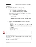
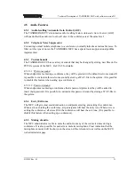
Incoming & Outgoing MCU calls: Normally the MCU will set up only 1 channel from PRI 1
and build up the channels starting from the 'bottom' of the last PRI in use.
This will ensure that the MCU always have available channels on the first PRI number (which
normally should be the MCUs main number).
The TANDBERG MCU supports simultaneous dial in to the same conference on ISDN.
4.2.2 H.221
•
For bit rates from 56 kbps up to 128 kbps (1 or 2 channels).
•
The maximum relative delay difference between the 2 B-channels is 0.6 second.
4.2.3 H0
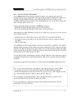
H0 is an ITU defined 384 kbps service available for ISDN PRI. The TANDBERG MCU
supports H0 that is defined as a group of 6 ISDN channels multiplexed to provide one 384 kbps
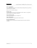
channel. H0 may have a shorter connection time, since there is only one channel to set up.
This service is sometimes called
Switched 384
or
ISDN H0
.

