background image

96

TANDBERG Videoconferencing System

Peripherals

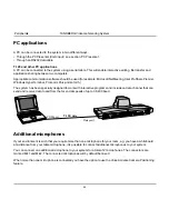
Additional microphones

If your environment is such that you require more than one microphone for your room, e.g. you have a whiteboard
at a distance from your table microphone, it is possible to connect additional microphones to your system.

You can connect one additional microphone to your system for a total of 2 microphones. The connectors are
marked Mic1 and Mic2. The connected microphones will by default be mixed.

When more than one microphone is connected you have the option to use the Voice Activate Camera Positioning
feature.

T.120 / data

Dataport 1

COM port

PC applications

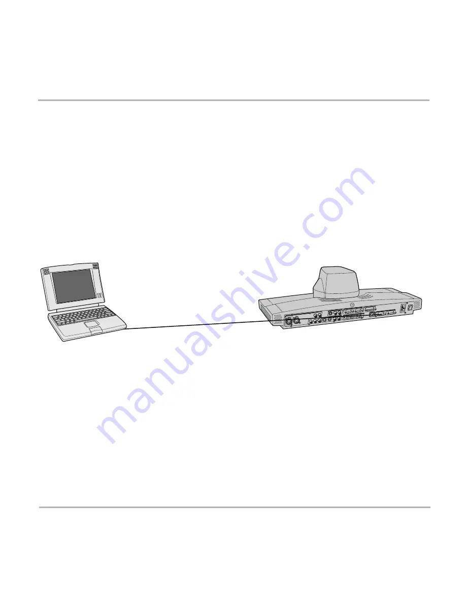
A PC can be connected to the system in two different ways.
• Through the PC Presenter (VGA input), see section ‘PC Presenter’.
• Through an RS232 data cable.

T.120 and other PC applications

A PC can be connected to the system using a serial cable. This will enable interactive editing, file transfer and
application sharing between two computers.

Appropriate communication software should be used (for example: Microsoft NetMeeting, Intel ProShare Premier,
Windows HyperTerminal, Procomm Plus and so forth.)

The system has been specially designed to work with interactive programs and includes a data channel that can
send and receive data to and from the far end at speeds of up to 38,400 baud.

Summary of Contents for Media Processing System MPS 800

Page 1: ...1 Software version B4 D12153 06 This document is not to be reproduced in whole or in part without permission in writing from UserManual...

Page 2: ...2 TANDBERG Videoconferencing System...

Page 3: ...or by any means electronically mechanically by photocopying or otherwise without the prior written permission of TANDBERG Nationally and internationally recognized trademarks and tradenames are the p...

Page 4: ...produce heat Grounding or Polarization Do not defeat the safety purpose of the polarized or grounding type plug A polarized plug has two blades with one wider than the other A grounding type plug has...

Page 5: ...ing and ending calls 20 Directory 25 General use 28 Adjusting volume 28 View outgoing video selfview 28 Microphone on off 28 Do Not Disturb Sleep Mode 29 Controlling the Main Camera 30 Selecting video...

Page 6: ...onfiguration 66 LAN Settings 73 Call Settings 80 Dataport configuration 82 Language 84 Software Options 84 Diagnostics 85 Peripheral Equipment 89 Interfaces 89 Dual Monitor 91 Document camera 92 Audio...

Page 7: ...ipants at the far end to simultaneously watch a presenter on one screen and a live presentation on the adjoining screen Digital ClarityTF participants enjoy presentations of exceptionally high quality...

Page 8: ...gs Ext network Settings Inputs Outputs AGC Settings Restore Audio Defaults Level Settings Level Settings Line 3 Setup Exit Diagnostics Focus Brightness Whitebalance Video Name VGA Settings Disconnect...

Page 9: ...TANDBERG Videoconferencing System 9 The TANDBERG 800 Videoconferencing System At a glance the TANDBERG 800 system...

Page 10: ...and data the transmission of this information to a remote site and the decompression of the incoming information Hence the name Codec Intelligent Call Management ICM and the SoftMux are features buil...

Page 11: ...pe is not approved for connection directly to the telecommunications network This network type is only to be used behind a PABX X 21 network type is not approved for connection directly to the telecom...

Page 12: ...TANDBERG Videoconferencing System Installation IMPORTANT THE CAMERA SHOULD BE ALIGNED WITH THE FRONT EDGE OF THE MONITOR TO ENSURE THE IR SENSOR IN THE CAMERA CAN PICK UP SIGNALS FROM THE REMOTE CONTR...

Page 13: ...ideo US Audio The cable with one RCA connector on one side and two RCA connectors on the other side Connect the two RCA connectors to your monitor Audio Left Right connectors the audio signal from the...

Page 14: ...th the socket to which ISDN cable number 1 is connected SOME SOFTWARE VERSIONS DO NOT SUPPORT THREE ISDN LINES NorthAmerica The TANDBERG 800 does not have a built in network terminator If your wall so...

Page 15: ...the number keys as on a mobile phone Select the language you want to use in Terminal Settings Language If you are using two monitors set Utilities Dual Monitor On To activate MultiSite and or Presente...

Page 16: ...d to be configured Press MENU on the remote control Select the menu Terminal Settings then Network Set Current Network to the network you want to use Specify the settings for the selected network in o...

Page 17: ...ol Select the menu Terminal Settings then LAN Settings Specify the necessary LAN settings according to the instructions from your LAN administrator If there is an H 323 Gatekeeper present on your LAN...

Page 18: ...sing the On Off switch located at the rear of the Codec see figure below After a few seconds you should see a Welcome menu on the monitor If this does not help verify that your monitor is switched on...

Page 19: ...creen The text inside the blocks will change depending on which menu is selected The three Quick Keys have different colors Preset keys Activate pre stored camera positions Video source keys Activate...

Page 20: ...channels are dropped during a meeting Downspeeding automatically maintains the connection without interrupting the call in progress The SoftMux also enables you to dial to other videoconferencing equ...

Page 21: ...tar after the number and then enter the sub address extension address Example 12345678 10 number Sub address extension address MCU password When calling to external MCU s requiring a password TSC 1 th...

Page 22: ...IP Move the indicator to the desired bandwidth then press the Select Quick Key You may also press the Set as Default Quick Key in order to make the selected bandwidth the default bandwidth for subsequ...

Page 23: ...quent calls If Auto is selected the system will select a network based upon the following criteria If an IP address e g 123 3 0 12 is entered LAN H 323 is selected If the first digits in the number ma...

Page 24: ...r facility is switched off See Utilities in Advanced use End a call To end a call press the DISCONNECT key Correcting keying mistakes To delete the last digit or character entered press the DELETE key...

Page 25: ...entries will not be displayed when you are in a call By using the dataport file system or external management systems like the TANDBERG Management Suite it is possible to store 200 additional entries...

Page 26: ...wo numbers are required both numbers should be specified 2x64 or 2x56 calls 3 Select Quality to specify call rate to be used 4 Select Net to specify the network profile to be used See Selecting settin...

Page 27: ...ONE WITH 128KBPS 1 SINCE ALL SITES MUST USE THE SAME BANDWIDTH QUALITY PER SITE WILL BE 128KBPS 2 IN ADDITION MAXIMUM BANDWIDTH PER SITE CANNOT EXCEED THE TOTAL BANDWIDTH AVAILABLE DIVIDED BY THE NUM...

Page 28: ...AUX AND VCR AUDIO INPUT 3 4 General use Adjusting volume Press the VOLUME keys to adjust the volume level An on screen indicator will show the current level View outgoing video selfview Press the SEL...

Page 29: ...line will indicate when Do Not Disturb is active When Sleep Mode is selected the following quick keys are displayed Pressing Sleep Now puts the monitors in sleep mode The system will still accept inc...

Page 30: ...Moving zooming camera To control the Main Camera use the keys below for pan tilt and for zooming IF THE MENU SYSTEM IS ACTIVE THE ARROW KEYS WILL NAVIGATE IN THE MENUS Focusing camera The Main Camera...

Page 31: ...essing CamTrack On in the Preset 0 9 menu which is activated by pressing the P button on the remote control An on screen indicator CamTrackOn will appear When activating another video source e g docum...

Page 32: ...presets To select a pre stored camera position audio and video source use the keys P1 P2 P3 or press P until the on screen indicator Preset 0 9 appears and use 0 9 to activate P0 P9 presets To exit Pr...

Page 33: ...far end camera use the keys below for pan tilt and for zooming Far end presets can be activated by pressing the keys P1 P2 P3 or the number keys 0 9 to activate presets P0 P9 Selection of far end vide...

Page 34: ...The last sent or received still image will automatically be displayed on your screen Press SELFVIEW to return to normal view REQUIRES AUTO DISPLAY STILL IMAGE ON IN PRESENTATIONS Receiving a still im...

Page 35: ...wing menu will be displayed Select video source to transmit on Duo Video Press CONNECT to add Duo Video AUTOMATIC DUO VIDEO HANDLES DUO VIDEO WITHIN THE SAME CALL IT IS NOT NECESSARY TO MAKE A NEW CAL...

Page 36: ...uo Video full screen Main source in PIP and vice versa Pressing SELFVIEW will not change anything on the main monitor Pressing MOVE PIP will move PIP only on the 2nd monitor Controlling the camera cha...

Page 37: ...Establishing a conference is done by first making a call to one site When a call is established with the first site the other sites are connected one by one It is possible to either dial out to the si...

Page 38: ...ms connect to two other video sites plus one audio site each These systems will automatically run Voice Switched mode and transmit a full screen image to the host when calling on ISDN When calling on...

Page 39: ...that you do not run out of bandwidth Example If the system has 512kbps available and you want to connect 3 sites in addition to the host 128kbps should be selected for the first call The system will t...

Page 40: ...mber 3 To dial in to the MultiSite on ISDN PRI Dial the main number of the system My ISDN Number All sites can dial the same number To dial in to the MultiSite on IP Dial the IP Number or the IP Addre...

Page 41: ...e to the VGA Output and that the PC transmits a supported VGA format see tip below Consult your PC operating manual to see how to transmit a VGA image from your PC typically Fn F5 PC Presenter input V...

Page 42: ...55 0 Gateway 196 9 200 21 See LAN Settings in Advanced use for further information Start your Web browser In the address field type the IP address of the codec The Web page of the codec will be shown...

Page 43: ...e communication software should be used for example Microsoft NetMeeting Intel ProShare Premier Windows HyperTerminal Procomm Plus and so forth The system has been specially designed to work with inte...

Page 44: ...move the highlighted bar to the desired sub menu or choice To confirm a highlighted selection press OK To return to the previous page press the key or select Previous Menu menu Advanceduse OK A MENU S...

Page 45: ...video for all video inputs Natural Video Auto Interlaced video capabilities iCIF will be transmitted and enabled Off Interlaced capabilities will not be transmitted Useful if far end can not handle th...

Page 46: ...compression Off No video is transmitted Resolution Auto The setting of Video Auto Motion Sharpness in Call Quality will be used see tip above 4CIF Digital Clarity 704 x 576 pixels only for H263 iCIF N...

Page 47: ...idth in use Motion Duo Video is optimized for smooth motion video This mode is ideal if the image from two W A V E cameras should be simultanously transmitted to the far end Sharpness Duo Video is opt...

Page 48: ...l Image source Select which video source Duo Video transmits If you want the document camera to be the default source when using Duo Video still images select Duo Video Still Image source DocCam To us...

Page 49: ...You must manually answer all incoming calls by pressing the CONNECT key Far end camera control On The far end will be able to Control your camera Select your video sources Activate your presets Reques...

Page 50: ...e active site will be displayed in full screen during a MultiSite conference Also called Voice Switched mode MCU status line On The MultiSite MCU DuoVideo indicators will be displayed and provide info...

Page 51: ...he same time Chairman Control functionality enables one participant to control the meeting by selecting which of the conference participants is to be broadcast to the other participants THIS SYSTEM HA...

Page 52: ...will change to Release Floor If View Site is selected View Site will change to End View Selecting Take Chair will send a request to take chair If granted the Quick keys will be If Floor to Site is se...

Page 53: ...choose Release Floor to take you Off Air You should do this when you wish to make the floor available to the other participants in the conference Terminal Names Allows you to see the site numbers or...

Page 54: ...se chair Allows you to relinquish the privileges of chairmanship of the conference Floor to site Allows the chairman to select which of the conference participants is to be broadcast to all other part...

Page 55: ...d 2 are intended for electret type microphones The microphone inputs are balanced with 24V phantom power Audio input 3 is intended for connection to external playback devices or to telephone add on hy...

Page 56: ...ent is connected The on screen audio level indicator will make it easier to set the correct input level settings The input level should be adjusted so that the average level reaches the preferred leve...

Page 57: ...ED IN THE SAME ROOM AS THE MICROPHONES CONNECTED TO THE SYSTEM DOING THIS WILL CAUSE HOWLING AND POSSIBLE DAMAGE TO THE SPEAKER SYSTEM If an output is Off no audio will be sent to that output Level Se...

Page 58: ...are very significant the echo canceller may take a second or two to re adjust You can choose to switch off the echo canceller for the available audio sources Noise Reduction In addition to echo cance...

Page 59: ...ed Carpets curtains etc might require lower settings Adjust the setting NOTE on the far end if one of the following symptoms occur There is still some echo of your own audio Increase the setting The s...

Page 60: ...well as the signal Therefore in noisy environments it is advisable to turn the leveller off Tips for improving the echo canceller performance Place all microphones as far as possible from the loudspe...

Page 61: ...o their factory default settings by using Restore Audio Defaults The echo canceller tries to estimate the echo path from the speaker system to the microphones Moving objects change this path therefore...

Page 62: ...Users of a document camera with an S video output can configure the system to activate an S video input when pressing doc cam on the remote control Video2 Video Input 2 S video will be activated when...

Page 63: ...to mode the whitebalance is continuously updated To update the whitebalance manually select Manual and press OK A WHITE OBJECT SHOULD BE HELD IN FRONT OF THE CAMERA A FEW SECONDS BEFORE AND AFTER SELE...

Page 64: ...4 will be disabled Loop VGA Out will display whatever is present on VGA In All video outputs will be enabled The VGA monitor will act as a third monitor VGA Out Quality VGA Out Quality changes the res...

Page 65: ...he next time you enter the menu Start using VNC To activate VNC press PC on the remote control Please make sure that PC is set to VNC in the Video Settings Menu See also PC SoftPresenter section for f...

Page 66: ...ify which network to use and define its settings If you want to use your system via ISDN BRI you should select Current Network ISDN BRI and enter the ISDN BRI Settings menu to set the BRI parameters I...

Page 67: ...NATIONAL ISDN IS SELECTED PRESS THE QUICK KEY AUTO BRI CONFIG TO REQUEST AN AUTOMATIC CONFIGURATION OF THE LINE SPID SETTINGS SWITCH MUST SUPPORT GR 2941 CORE 1TR6 SHOULD ONLY BE USED IF YOU ARE OPER...

Page 68: ...are not to be used set Enabled Off Line 1 should always be enabled National ISDN and AT T Custom ISDN might require SPID numbers associated with your ISDN numbers If you have received two different S...

Page 69: ...same ISDN telephone number and line The terminals are addressed by using different subaddresses To call a terminal with a subaddress separate the ISDN telephone number and the subaddress with a Exampl...

Page 70: ...allel when setting up a BONDING call Off Channels will be dialed one by one which may increase the dialing time Send Own Numbers On The system will send its own numbers to the far end Off The system w...

Page 71: ...ing RS449 V35 Compatible when the external equipment uses RS366 ports Leased Line is a non dialing protocol and should be used when two codecs are connected in a point to point connection Use Leased L...

Page 72: ...h transmit and receive Cable Specification V 35 V 35 RS 366 cable Signal Name Female Male 34pin Male 25pin Comments 26pin DSUB Winchester DSUB Pin number Pin number Frame ground 1 A Signal ground 19 2...

Page 73: ...ient to know which stream to receive If the first codec streams on port 2240 and the second codec on port 2250 the client has to specify which port to listen to Video is transmitted on the specified p...

Page 74: ...ming client e g a PC to connect to the codec s streaming session Used by Cisco IP TV Off No announcement packets will be transmitted Video Rate Defines the Video streaming rate from the system Range i...

Page 75: ...dec within 30 seconds this specific gatekeeper will be used If no gatekeeper responds the codec will not use a gatekeeper for making H 323 calls and hence an IP address must be specified manually Manu...

Page 76: ...e TOS Helps a router select a routing path when multiple paths are available Delay Tells the router to minimize the delay Throughput Tells the router to maximize the throughput Reliability Tells the r...

Page 77: ...to an external videoconferencing system when the IP traffic goes through an NAT router When NAT is On the NAT Server Address will be shown in the startup menu My IP Address 10 0 2 1 NAT NATAddress Thi...

Page 78: ...nes the network address of the codec This address is only used in static mode In DHCP mode the assigned IP address can be found on the Welcome Menu IP subnet mask IP subnet mask defines the type of ne...

Page 79: ...it is sufficient to use this Quick key to restart the system NOTE SNMP Trap Host SNMP Simple Network Management Protocol is used for monitoring and configuring of different units in a network The code...

Page 80: ...em will accept incoming telephone calls Off The system will not accept incoming telephone calls This is useful to prevent incoming calls from systems other than videoconferencing systems Fallback to t...

Page 81: ...seconds during which an open padlock will be displayed When encryption has been established a closed padlock symbol will be displayed Off The system will not send or receive encrypted data Technical e...

Page 82: ...ANDBERG system at the far end Control mode The control interface provided by the Dataport supports a subset of the Hayes command set as well as a comprehensive set of system specific commands This mod...

Page 83: ...o Data mode When the call disconnects Dataport 1 switches back to Control Mode T 120 Provides a data channel supporting the T 120 standard for data communication Using T 120 software on your PC you ca...

Page 84: ...activate MultiSite and or Presenter functionality A restart of the system is required after entering a new option key If the option key is invalid the original key will be used Language The system su...

Page 85: ...ss is available through the Channel Status window This window indicates the various stages each B channel goes through whilst establishing a connection Status BRI Comments Idle the channel is idle Cal...

Page 86: ...ted unassigned number 2 No route to specified transit network WAN 16 Normal clearing 17 User busy 18 No user responding 21 Call rejected 28 Invalid number format incomplete number 29 Facility rejected...

Page 87: ...FAULT SETTING WILL NOT AFFECT YOUR CALL DIRECTORY INFORMATION NETWORK TYPE LINE SETUP NUMBERS OR YOUR SPID NUMBERS NOTE Call status Comprehensive information about the call is available through the Ca...

Page 88: ...ar end in loop The far end will see and hear the local side varies depending on implementation of loop functionality The local side will see its own video and hear its own audio if the far end support...

Page 89: ...ou will be able to build your own applications for use with the TANDBERG 800 thereby better integrating the system into your business environment This chapter will explain how to connect peripheral eq...

Page 90: ...lt by the monitors The outputs are always active The format of the output will be either PAL or NTSC depending on your country s standard video format 4 Audio Inputs 2 microphone inputs balanced 24V p...

Page 91: ...creen selfview still images and Duo Video To use the system in the Dual Monitor configuration Connect Video Out 2 preferably otherwise 4 on the system to a video input on the dual monitor Set Dual Mon...

Page 92: ...a to the DocCam input on the Codec Press DOC CAM on the remote control to select the document camera as the video source See also Presentations for easy access to still image transfer from document ca...

Page 93: ...efined by a quarter sphere of approximately 14 foot 4 25m radius extended in front of and to the sides of the microphone Please contact your TANDBERG representative for further information Tracker The...

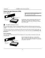
Page 94: ...in the local speaker system The audio from the VCR and your microphone s will be mixed and sent to the far end When a person talks the VCR audio level will be reduced to make it easier to comment on a...

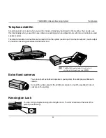
Page 95: ...arked AUX on the system audio input 3 and audio output 2 Audio output 2 provides a mixed signal between local and far end Extra fixed cameras You can connect extra fixed cameras to your system for exa...

Page 96: ...te Camera Positioning feature T 120 data Dataport 1 COM port PC applications A PC can be connected to the system in two different ways Through the PC Presenter VGA input see section PC Presenter Throu...

Page 97: ...TANDBERG can provide NT adapters For convenience the NT1 adapters could be placed inside the cabinet If needed use the shorter ISDN cable RJ45 connectors delivered with the NT1 between the codec and...

Page 98: ...onfiguration of the Telesync Adapter is necessary Configuration of the system Select network type to National ISDN LINE 1 SETUP NUMBER1 program with number from the first SW56 line NUMBER2 program wit...

Page 99: ...results Avoid harsh side lighting or strong light from above Strong sunlight from a window or skylight may put part or all of the subject matter in shadow or cause silhouetting If you still have prob...

Page 100: ...e possibility of somebody inadvertently walking into the camera s field of view when entering the room Other than the conference participants there should be no moving items in the sent image system G...

Page 101: ...t to the system you want to upgrade using ISDN Copy the software file to a folder on your harddisk Open a DOS window and go to this folder Type ftp IP address of your local codec Enter password Releas...

Page 102: ...ut validation E g you can enter whatever code you want and have access to the system The access txt file is a plain text file with one line per access code as shown below 1234 1250 A1 B2 ABC To upload...

Page 103: ...TANDBERG Videoconferencing System 103 Appendices Appendix 6 Declaration of Conformity...

Page 104: ...3 Correcting keying mistakes 24 D Data mode 82 Dataport configuration 82 Declaration of Conformity 102 103 DHCP 78 Diagnostics 85 Dial in to MultiSite 40 Dialing 20 Digital Clarity 47 Directory Add N...

Page 105: ...53 Request floor 53 Requesting a still image 34 Restart 79 Restore Audio Defaults 61 Restore defaults 87 Restrict 99 Restricted call 22 S Seating Area 100 Selecting network 23 Selecting video sources...

Page 106: ...deo 45 input 62 inputs 30 90 mode 46 outputs 90 sources 30 Video call 20 Video cassette recorder VCR 94 Video In Name 63 View current settings 88 outgoing video 28 Viewing a still image 34 VNC 62 VNC...

Reviews: