Equipment Description
Reference Guide: SM6610, SM6615, SM6620 and SM6625 Satellite Modulators
Page 7-7
ST.RE.E10152.2
A switchable 24 V dc power supply and 10 MHz reference frequency are
combined with the L-band output for use by an external block up-converter
(BUC).
7.3.4
S11340 Host Controller Card
The microprocessor on the Host Controller Card is responsible for the
communication, configuration and monitoring functions performed by the
Modulator. It supports RS-232/485 remote control, Ethernet control,
VT100 terminal control and front panel control. Errors and alarms can be
reported via any of the aforementioned interfaces and via a simple
RESET/STATUS relay interface.
The embedded software in the Modulator also enables the user to upgrade
all of the software and firmware in the unit (via FTP) without having to
remove the chassis cover. In case of an external error in the data stream
or power supply the Modulator will always restore its last working state
when all the external errors are cleared. The embedded software controls
this recovery. For an explanation of all the control and monitoring features
refer to Chapter 3, Operating the Equipment Locally.
7.3.5
S13450 DVB ASI & SPI Input Card (Option)
Transport Stream Interface
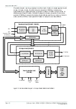
The S13450 DVB ASI & SPI Input card can receive DVB-compliant MPEG-2
transport streams via either the Synchronous Parallel Interface (SPI) or
the two Asynchronous Serial Interfaces (ASI). The user can connect a
stream into any of the three interfaces.
It is also possible to connect two inputs; for example, it is possible to
connect a stream into both ASI Inputs. This is useful if two distinct
distribution systems are available to carry the transport stream from the
multiplex source; in case of failure on one distribution system the other
will still carry the data to be transmitted. The Modulator can be made to
switch if the input in use suffers a failure, although automatic switching is
not currently supported.
The S13450 card can accept transport streams in any of three different
data formats:
•
188-byte packets consisting of 188 contiguous data bytes
•
204-byte packets consisting of 188 data bytes and 16 RS coding bytes
(the coding bytes are ignored)
•
204-byte packets consisting of 188 data bytes and 16 dummy packets
Transport stream rate adaptation or de-jittering is performed on the
Baseband card.
Additional ASI Information
The encoded line rate of the ASI stream is 270 MBaud
±
100 ppm. All ASI
bytes must be 8B/10B encoded as specified by ETSI standard EN 50083-9.
Special comma characters, K28.5 code words are used as byte
synchronisation patterns. Two consecutive K28.5 code words are
transmitted prior to each MPEG-2 packet and subsequent K28.5 code
words are inserted to pad the data to achieve the required encoded ASI
line rate.

