Introduction
Page 1-10
Reference Guide: SM6610, SM6615, SM6620 and SM6625 Satellite Modulators
ST.RE.E10152.2
1.7 Guided
Tour
1.7.1 Construction
The Modulator is constructed using a shielded self-ventilated enclosure. All
inputs and outputs are via rear-panel connectors. The unit may be
operated freestanding or mounted in a 19-inch rack; 1U rack height is
required.
1.7.2
Controls and Indicators
Operating Controls
The Modulator may be controlled by the LCD display and pushbutton
keypad. The front panel offers a choice of two interface levels, either
monitoring only or full access control (refer to Chapter 4, Front Panel
Control).
Front Panel Indicators
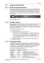
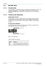
The Modulator provides two LED indicators. These are located at the
left-hand side of the unit (see Figure 1.4).
Figure 1.4: Front Panel LEDs
Table 1.3: Modulator LED Indicators
Indicator Description
Alarm
The red LED indicates when an alarm condition is present.
Power
The green LED is illuminated when ac power is applied.
Green Power LED
Red Alarm LED

