Installing the Equipment
Page 2-6
Reference Guide: SM6610, SM6615, SM6620 and SM6625 Satellite Modulators
ST.RE.E10152.2
2.3
Mains Operating Voltage, Fusing and Earthing
2.3.1 AC
Power
Supply
The Modulator operates from a wide-ranging mains power supply
(100-120 V or 220-240 Vac 50/60 Hz nominal) and is designed for use in
ambient air temperature in the range 0
°
C to +50
°
C. There are no links etc.
to be altered for operation from different supply voltages. The full
Technical Specification is given in Annex B, Technical Specification.
WARNING…
THIS EQUIPMENT SHOULD ONLY BE OPERATED FROM THE TYPE OF POWER SOURCE
INDICATED ON THE MARKING LABEL. IF YOU ARE NOT SURE OF THE TYPE TO YOUR
BUSINESS, CONSULT YOUR APPLIANCE DEALER OR LOCAL POWER COMPANY. DO NOT
OVERLOAD WALL OUTLETS AND EXTENSION CORDS AS THIS CAN RESULT IN A RISK OF FIRE
OR ELECTRIC SHOCK.
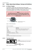
Figure 2.2: AC Power Inlet Assembly
Table 2.1: Fuse Information
Item Specification
Fuse
Single pole, fitted in live conductor in power input filter at rear of unit.
Fuse type
5 mm x 20 mm anti-surge (T) HBC, IEC/EN 60127-2 Sheet 5
Fuse rating
5 A
Fuse rated voltage
250 Vac
Power lead connector fuse (if appropriate) 5 A minimum
NOTE...
See Annex B, Technical Specification for more fuse information.
2.3.2 Technical
Earth
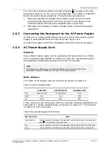
Figure 2.3: Location of the Technical Earth
AC Power Inlet
Fuse Carrier
To access the fuse, ease out the notch with
a small flat-blade screwdriver.
NOTE...
The Technical Earth terminal is the 6 mm tab connector.
Position of the
Technical Earth

