Installing the Equipment
Page 2-12
Reference Guide: SM6610, SM6615, SM6620 and SM6625 Satellite Modulators
ST.RE.E10152.2
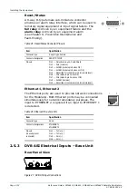
Reset/Status
A 9-way D-type female sub-miniature connector
provides an alarm relay interface, which can be used to
remotely signal equipment or input signal failure. The
fail relay is driven by an equipment failure and the
alarm relay is driven by an equipment alarm
(see Chapter 8, Preventive Maintenance and
Fault-finding).
Table 2.5: Reset/Status Connector Pin-outs
Item Specification
Connector type
9-way D-type, Female
Connector designation
RESET / STATUS
Pin-outs
Pin 1
Protective Ground - Cable Shield
Pin 2
FAIL (common)
Pin 3
ALARM (make to pin 8 when OK)
Pin 4
ALARM (make to pin 8 when not OK)
Pin 5
Reset (line 2) (connect to pin 9 for remote reset)
Pin 6
FAIL (make to pin 2 when OK)
Pin 7
FAIL (make to pin 2 when not OK)
Pin 8
ALARM (common)
Pin 9
Reset (line 1) (connect to pin 5 for remote reset)
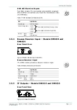
Ethernet 1, Ethernet 2
The Ethernet ports are used to provide network connections
for the Modulator. Both Ethernet ports may be connected
simultaneously for network redundancy purposes. The
input to ETHERNET 2 is ignored if an input to ETHERNET 1
is detected.
Table 2.6: Ethernet Pin-outs (2 off)
Item Specification
Connector type
RJ-45
Connector designations
ETHERNET 1
ETHERNET 2
Pin-outs
(Unused pins not
connected)
Pin 1
Tx Out (
+
)
Pin 2
Tx Out (
−
)
Pin 3
Rx In (
+
)
Pin 6
Rx In (
−
)
2.5.3
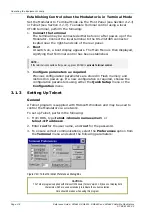
DVB ASI Electrical Inputs – Base Unit
Rear Panel View
Figure 2.7: DVB ASI Input Connections

