background image


Operating the Equipment Locally – Main Menu Option 4: System Menu 

Reference Guide: SM6610, SM6615, SM6620 and SM6625 Satellite Modulators 

Page 3-37 

ST.RE.E10152.2 

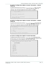
Serial Port Configuration Option 4: Select Termination – RS-232 
Interface 
Type 4 at the prompt to view the 

Select Termination

 menu from the 

Serial Port Configuration Menu

. When the RS-232 interface is 

selected, only the high impedance (Hi-Z) option is available. 


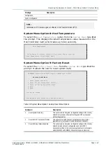
        Select Termination 


   Serial Port is terminated by Hi-Z 


 Cannot set termination in RS-232 Mode 

 Press Enter to continue 

Serial Port Configuration Option 4: Select Termination – RS-485 
Interface 
Type 4 at the prompt to view the 

Select Termination 

menu from the 

Serial Port Configuration Menu

. Selecting 100 Ohms switches in 

100 

 line termination resistors at the RS-485 line receiver inputs. 


 Select Termination 


   Serial Port is terminated by Hi-Z 


 1  Hi-Z 

 2  100 Ohms 


 Please enter your selection, then press Enter: 

Serial Port Configuration Option 5: Select Baud Rate 
Type 5 at the prompt to view the 

Select Baud Rate

 menu from the 

Serial Port Configuration Menu

. This option allows the speed of the 

RS-232/485 port to be set between 300 and 38400 Baud. 


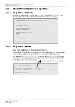
  TANDBERG Television SM6600 Satellite Modulator: DEV001 


Select Baud Rate 


  1 300 Baud 

  2 600 Baud 

  3 1200 Baud 

  4 2400 Baud 

  5 4800 Baud 

  6 9600 Baud 

  7 19200 Baud 

  8 38400 Baud 

  Q Quit 


Status: No Alarms 


Please enter your selection, then press Enter: 

Summary of Contents for SM6610

Page 1: ...ST RE E10152 2 Issue 2 ENGLISH UK REFERENCE GUIDE SM6610 SM6615 SM6620 and SM6625 Satellite Modulators Software Version 2 0 and later SM6610 SM6615 SM6620 and SM6625 Satellite Modulators...

Page 2: ...ndlich sein dann BEDIENEN SIE DIESE GER TE NICHT Eine bersetzung des Handbuches in diese Sprache ist gegen Berechnung lieferbar ESPA OL LEA ESTE AVISO PRIMERO Si no entiende el contenido de este manua...

Page 3: ...s the menus screens and options available to the user and details the setting up configuration operating and monitoring procedures Chapter 5 RS 232 Remote Control Protocol Describes the RS 232 Remote...

Page 4: ...e Date Software Version Comments 1 Jun 2004 1 1 Initial Issue 2 Jan 2005 2 0 Updated for software v2 0 which supports transport stream rate adaptation The following manuals are also associated with th...

Page 5: ...IVE INFORMATION WHICH IF STRICTLY OBSERVED WILL PREVENT PERSONAL INJURY OR DEATH OR DAMAGE TO PERSONAL PROPERTY OR THE ENVIRONMENT THEY ARE BOXED AND SHADED FOR EMPHASIS AS IN THIS EXAMPLE AND ARE PLA...

Page 6: ...ng TANDBERG Television Service Support For stand alone equipment then TANDBERG Television BASIC Advantage is the value for money choice for you BASIC provides you with year by year Service long after...

Page 7: ...l Address training tandbergtv com Internet Address http www tandbergtv com Customer Services and Technical Training Postal Address Tandberg Television Unit 2 Strategic Park Comines Way Hedge End South...

Page 8: ...Preliminary Pages Page viii Reference Guide SM6610 SM6615 SM6620 and SM6625 Satellite Modulators ST RE E10152 2 BLANK...

Page 9: ...5 2 Non DVB Applications 1 8 1 6 Additional Features for Greater Flexibility 1 9 1 6 1 Spectrum Sense 1 9 1 6 2 Control and Monitoring 1 9 Local Control 1 9 Remote Control 1 9 User Selectable Function...

Page 10: ...Introduction Page 1 2 Reference Guide SM6610 SM6615 SM6620 and SM6625 Satellite Modulators ST RE E10152 2 BLANK...

Page 11: ...e Chapter 3 In the Main menu by selecting option 7 Software Update menu and then from there choosing option 3 Display Code Versions In the Test menu by selecting option 3 Version and Build Information...

Page 12: ...Serial Number A unique number given to the unit Unit Configuration Number The unit configuration number is in two parts separated by a dash The first part is the E number of the base unit before optio...

Page 13: ...nform to the DVB Asynchronous Serial Interface DVB ASI standard and optionally the DVB Synchronous Parallel Interface DVB SPI standard if the SM66XX HWO ASI SPI option is fitted The Modulator can be c...

Page 14: ...CR correction allowing it to be used at a fixed symbol rate irrespective of the transport stream input data rate Rate adaptation may be switched on or off under user control See Section 7 3 2 Transpor...

Page 15: ...rent compromises between bit rate and ruggedness For 8PSK and 16QAM modulations pragmatic trellis coded modulation PTCM is used PTCM code rates of 2 3 5 6 and 8 9 are available with 8PSK modulation PT...

Page 16: ...play and 6 button keypad RS 232 485 control backwards compatible with System 3000 and evolution 5000 SM5600 Satellite Modulators Dual redundant 10BaseT Ethernet control Software and firmware easily up...

Page 17: ...erminal or a PC running appropriate software using the RS 232 485 port Remote Control In addition to the RS 232 485 port remote control is possible using either one of the Ethernet ports The user may...

Page 18: ...ing Controls The Modulator may be controlled by the LCD display and pushbutton keypad The front panel offers a choice of two interface levels either monitoring only or full access control refer to Cha...

Page 19: ...0 Modulator Rear Panel Figure 1 6 View of the SM6615 Modulator Rear Panel Figure 1 7 View of the SM6620 Modulator Rear Panel Figure 1 8 View of the SM6625 Modulator Rear Panel 1 8 Input Option Module...

Page 20: ...t Port 1 or 2 Ensure the terminal is switched on and operational see Chapter 3 Operating the Equipment Locally for instructions on how to establish control from the local terminal or from the remote t...

Page 21: ...4 1 General 2 8 2 4 2 Transport Stream Input 2 9 2 4 3 L Band Input Available Only on L Band Output Models SM6615 and SM6625 2 9 2 4 4 Beacon Receiver Input Available Only on PREKOR Models SM6620 and...

Page 22: ...7 DVB ASI Input Connections 2 12 Figure 2 8 Beacon Receiver Input Connections 2 13 Figure 2 9 IF Output Connections 2 13 Figure 2 10 L Band Input and Output Connections 2 14 Figure 2 11 S13450 DVB AS...

Page 23: ...hanical Inspection Inspect the equipment for damage in transit If in doubt please contact TANDBERG Customer Services see Preliminary Pages WARNING REMOVING THE COVERS OF THIS EQUIPMENT MAY INVALIDATE...

Page 24: ...odulator should never be placed near or over a radiator or other source of heat It should not be placed in a built in installation such as a rack unless proper ventilation is provided and the instruct...

Page 25: ...storm or when it is left unattended and unused for long periods of time unplug it from the supply outlet and disconnect the antenna or cable system This will prevent damage to the product due to light...

Page 26: ...RE NOT SURE OF THE TYPE TO YOUR BUSINESS CONSULT YOUR APPLIANCE DEALER OR LOCAL POWER COMPANY DO NOT OVERLOAD WALL OUTLETS AND EXTENSION CORDS AS THIS CAN RESULT IN A RISK OF FIRE OR ELECTRIC SHOCK Fi...

Page 27: ...ed plug suitable for either the USA UK mainland Europe or Australia New Zealand as advised at the time of ordering NOTE The Modulator is not fitted with an ac power supply ON OFF switch Ensure the soc...

Page 28: ...Connections for pin out details of the unit connectors Unused connectors on this equipment do not need to be terminated Figure 2 4 Equipment Connections IF Output Models SM6610 and SM6620 SM6610 SM66...

Page 29: ...n L Band Output Models SM6615 and SM6625 If required connect the L BAND IN connector to the output of an auxiliary modulator using good quality coaxial cable with a characteristic impedance of 50 This...

Page 30: ...nce frequency output If required connect the L BAND OUT MONITOR connector either to a spectrum analyser or to an IRD for local monitoring purposes 2 4 6 Local Remote Control Select a method for config...

Page 31: ...either a local terminal control or remote control port Table 2 4 RS 232 485 Connector Pin outs Item Specification Connector type 9 way D type Male Connector designation RS 232 485 Pin outs RS 232 Conn...

Page 32: ...ommon Pin 3 ALARM make to pin 8 when OK Pin 4 ALARM make to pin 8 when not OK Pin 5 Reset line 2 connect to pin 9 for remote reset Pin 6 FAIL make to pin 2 when OK Pin 7 FAIL make to pin 2 when not OK...

Page 33: ...I IN 2 ASI IN 3 ASI IN 4 Pin outs Centre Shield Signal Ground Chassis 2 5 4 Beacon Receiver Input Models SM6620 and SM6625 Rear Panel View Figure 2 8 Beacon Receiver Input Connections Beacon Receiver...

Page 34: ...cket provides an IF output used for monitoring Table 2 10 IF Output Connector Monitor Item Specification Connector type BNC 75 Female Type Analogue Connector designations IF OUT MONITOR Pin outs Centr...

Page 35: ...t Ground L Band Output Monitor 75 F type socket provides an L band output used for monitoring Table 2 13 L Band Output Connector Monitor Item Specification Connector type F type 75 Female Type Analogu...

Page 36: ...connector provides a DVB compliant synchronous parallel interface Table 2 15 DVB SPI Connector Pin outs Item Specification Connector type 25 way D type Female Connector designation SPI IN Pin outs Pin...

Page 37: ...d power up the unit as follows 1 Power up the Modulator by turning on the local mains supply The unit executes a series of power up initialisation and self test routines 2 Ensure that all cooling fans...

Page 38: ...Installing the Equipment Page 2 18 Reference Guide SM6610 SM6615 SM6620 and SM6625 Satellite Modulators ST RE E10152 2 BLANK...

Page 39: ...dulation 3 15 Quick Setup Menu Option 8 FEC Rate 3 15 Quick Setup Menu Option 9 Roll off 3 15 Quick Setup Menu Option 10 IF Frequency 3 16 Quick Setup Menu Option 11 Uplink Freq 3 16 Quick Setup Menu...

Page 40: ...Test Menu Option 3 Version and Build Information 3 48 Test Menu Option 4 Test Relays 3 49 Test Menu Option 5 Test LCD 3 49 Test Menu Option 6 Test Keypad 3 49 Test Menu Option H Help 3 50 Test Menu O...

Page 41: ...e Modulator or terminal control can be used over a network using Telnet 3 1 2 Setting up the VT100 Terminal Emulation Program General To use the VT100 terminal emulation program it is necessary to set...

Page 42: ...0 ANSI and click OK Figure 3 3 Terminal Preferences Dialog Box 6 From the Settings menu choose Terminal Preferences see Figure 3 3 7 Set the parameters as in Figure 3 3 and click OK 8 From the File me...

Page 43: ...95 98 NT 4 0 XP proceed as follows 1 Select the Terminal program by accessing it through Start Program Accessories Communications HyperTerminal 2 Choose the icon and name for the terminal connection...

Page 44: ...changing This displays the Properties dialog box Select the Settings tab to display the dialog box shown in Figure 3 7 Figure 3 7 SM6600 Terminal Properties Dialog Box If the ASCII settings require ch...

Page 45: ...do not require resetting unless the configuration has not been saved prior to exiting the program Terminal Connection and Protocol The Terminal control port is configured as a Data Terminal Equipment...

Page 46: ...ctivate Terminal control 3 Configure parameters as required Previous configuration parameters are stored in Flash memory and restored on power up If a new configuration is required choose the configur...

Page 47: ...rs with User Management privileges see Section 3 7 System Menu Manage User Accounts for details 3 2 Navigating the Display Screens 3 2 1 Booting At switch on the Modulator runs through a boot sequence...

Page 48: ...3 12 Example Boot Display 3 2 2 Navigating the Menus Each of the menu screen choices is accompanied by a number Press the associated number followed by Enter to select the required command or option T...

Page 49: ...t Size 188 bytes 3 Rate Adapt OFF 4 Bit Rate 27 647059 Mbit s 5 Symbol Rate 20 000000 Msym s 6 Coding Mode DVB 7 Modulation QPSK 8 FEC Rate 3 4 9 Roll off 35 10 IF Frequency 70 000 MHz 11 Uplink Freq...

Page 50: ...ach of the options on this top level menu provide access to further sub menus see the following headings NOTES 1 Certain functionality of the Modulator is dependent upon the specific Modulator model t...

Page 51: ...ter your selection then press Enter NOTES 1 The options available in this menu their numbering and the ranges of some parameters are dependent upon the specific Modulator model the hardware options fi...

Page 52: ...ansport stream input bit rate Its range is variable dependent upon other parameters and options When a Bit Rate value is entered the corresponding value of Symbol Rate is automatically calculated and...

Page 53: ...e transmission process to be corrected at the receiver see Chapter 7 Equipment Description Forward Error Correction and Interleaving for further information Six FEC options are provided a value of 1 2...

Page 54: ...rter that is used in the satellite earth station to frequency up convert the Modulator s IF output The parameters IF Frequency and Uplink Freq are interrelated when an Uplink Freq value is entered the...

Page 55: ...F Spectrum When IF Spectrum is set to Normal the modulation at the IF Output of the Modulator is in accordance with ETSI standards EN 300 421 DVB S and or EN 301 210 DVB DSNG as appropriate When set t...

Page 56: ...MHz frequency reference which may be used by an external BUC UpConv Ref Current Value OFF 1 OFF 2 ON Quick Setup Menu Option 17 SM6620 Option 19 SM6625 PREKOR Menu The PREKOR Menu option is available...

Page 57: ...ve Alarms 2 Edit Alarm Mask H Help Q Quit Status No Alarms Please enter your selection then press Enter 3 5 2 Alarms Menu Options Alarms Menu Option 1 View Active Alarms Type 1 at the prompt to displa...

Page 58: ...FAIL 15V PSU Voltage Low 26 FAIL Hardware Fail 13 FAIL 15V PSU Voltage High 27 FAIL FPGA Configuration Fail 14 FAIL Backplane not Responding Q Next Block Status No Alarms Please enter your selection...

Page 59: ...rence Guide SM6610 SM6615 SM6620 and SM6625 Satellite Modulators Page 3 21 ST RE E10152 2 Alarms Menu Option H Help Type H at the prompt to view information about the options on the Alarms Menu Alarms...

Page 60: ...selection then press Enter 3 6 2 Configuration Menu Options Configuration Menu Option 1 View Current Configuration To select the View Current Configuration option from the Configuration Menu type 1 at...

Page 61: ...in the Flash memory Up to eight user configurations can be stored and later recalled without having to individually select the parameters each time Enter the configuration number 0 8 NOTE Configuratio...

Page 62: ...ored Configuration option from the Configuration Menu type 5 at the prompt This allows any of the previously stored configurations to be activated Activate Stored Configuration Config_0 Name Current A...

Page 63: ...9 Config_7 is Empty Config_8 is Empty Config_9 Name Default Author system JUN 01 2004 13 05 47 To Skip deletion of any Configuration Press CR only Select Stored Config to Delete Enter Config Number 1...

Page 64: ...01 2004 13 48 09 Config_3 Name Third Author system JUN 01 2004 13 48 09 Config_4 Name Fourth Author system JUN 01 2004 13 48 09 Config_5 Name Fifth Author system JUN 01 2004 13 48 09 Config_6 Name Si...

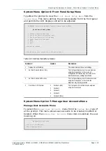
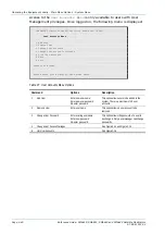
Page 65: ...9 Factory Reset H Help Q Quit Status No Alarms Please enter your selection then press Enter 3 7 2 System Menu Options System Menu Option 1 Modulator Identity Changing the Modulator Identity To display...

Page 66: ...RG Television SM6600 Satellite Modulator DEV001 Time and Date Menu 1 Display Current Time and Date 2 Set Time and Date 3 Setup Network Time Server 4 Date Format H Help Q Quit Status No Alarms Please e...

Page 67: ...to return to the Time and Date Menu Time and Date Option 2 Set Time and Date Setting the Time Locally If the time and date is not to be downloaded from the network it must be entered manually using th...

Page 68: ...ocol SNTP Do you want to change it Y N Type Y to change the protocol Time and Date Option 3 Setup Network Time Server Changing the Time Protocol The Modulator supports both the Time and SNTP Simple Ne...

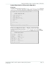
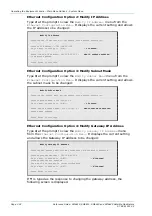
Page 69: ...ettings 2 Modify IP Address 3 Modify Subnet Mask 4 Modify Gateway IP Address 5 Display Ethernet Port Usage 6 SNMP Setup H Help Q Quit Status No Alarms Please enter your selection then press Enter Ethe...

Page 70: ...It displays the current setting and allows the subnet mask to be changed Modify Subnet Mask Changing the Subnet mask may terminate this network connection Current subnet mask 255 255 240 0 Do you want...

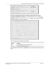
Page 71: ...et Configuration Option 5 Display Ethernet Port Usage Type 5 at the prompt to view the Display Ethernet Port Usage screen from the Ethernet Configuration Menu It displays the status of the two Etherne...

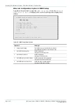
Page 72: ...SNMP alarm text mode to Verbose 5 Set SNMP alarm text mode to Terse H Help Q Quit Status No Alarms Please enter your selection then press Enter Table 3 3 SNMP Setup Menu Options Command Messages 1 Di...

Page 73: ...ion SM6600 Satellite Modulator DEV001 Serial Port Configuration Menu 1 Display Current Settings 2 Set Port Mode 3 Select Interface 4 Select Termination 5 Select Baud Rate 6 Select RS 485 Address H Hel...

Page 74: ...t Mode to Terminal Port mode updated This change requires the modulator to be rebooted Select this option to allow control of the Modulator by means of a VT100 terminal 2 Set Mode to Remote Port mode...

Page 75: ...terface Type 4 at the prompt to view the Select Termination menu from the Serial Port Configuration Menu Selecting 100 Ohms switches in 100 line termination resistors at the RS 485 line receiver input...

Page 76: ...wer on Self Test Menu Type 5 at the prompt to view the Power on Self Test Menu from the System Menu This menu allows the self test executed at power on to be enabled or disabled TANDBERG Television SM...

Page 77: ...ent Settings This screen displays the current settings 2 Set Front Panel to Monitor Only The front panel display is set to view only mode using this menu option In this mode all configuration informat...

Page 78: ...ts H Help Q Quit Status No Alarms Please enter your selection then press Enter Table 3 7 User Accounts Menu Options Command Options Description 1 Add User Enter new user name Enter new user password R...

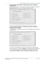
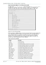
Page 79: ...igure 3 14 User Accounts Menu Option 4 Change User Access Privileges New Account User Accounts Menu Option 4 Change User Access Privileges Changing User Privileges To add the right to login via Telnet...

Page 80: ...be deleted however if the password has been changed attempting to delete the account will reset the password to the default Table 3 8 User Account Privileges Privilege Description FTP login User can...

Page 81: ...et system data TANDBERG Television SM6600 Satellite Modulator DEV003 Factory Reset Menu 1 Reset System Data Only 2 Reset All DPC Transponder Profiles 3 Reset All Except Networking Data H Help Q Quit S...

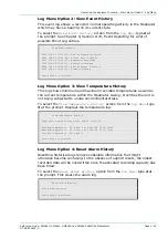
Page 82: ...History 6 Reset Temperature History H Help Q Quit Status No Alarms Please enter your selection then press Enter 3 8 2 Log Menu Options Log Menu Option 1 View Alarm History The alarms log indicates ir...

Page 83: ...perature History This log shows minimum and maximum recorded temperatures as well as the current temperature within the Modulator casing It verifies the unit is not being subjected to undue environmen...

Page 84: ...emperature History Temperature log reset Press Enter to continue Log Menu Option H Help Type H at the prompt to view information about the options on the Log Menu Log Menu Option Q Quit Type Q at the...

Page 85: ...ckly tests correct operation of the NVRAM in the Modulator Quick NVRAM Test Testing NVRAM Passed Test Passed Press Enter to continue Test Menu Option 2 Full NVRAM Test This option is similar to the Qu...

Page 86: ...al numbers Identifying Name DEV001 Unit Inventory Serial No 1 Unit Initialisation Date MAY 16 2003 15 09 02 Last Boot Time JAN 31 2005 14 00 07 Controller Card PCB Revision 3 Modification Status 0 Ser...

Page 87: ...nue Alarm relay CLEAR Fail relay SET Press Enter to continue Both relays SET Press Enter to continue Test complete Press Enter to continue Test Menu Option 5 Test LCD Type 5 at the prompt to select th...

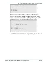
Page 88: ...Main Menu This menu provides options for the following TANDBERG Television SM6600 Satellite Modulator DEV001 Software Update Menu 1 Validate Newly Downloaded Code 2 Switch To Backup Code 3 Display Co...

Page 89: ...ersion is retained as a backup copy This option allows the user to revert to that earlier software version Selecting this option will display the details of the previous version of code loaded into th...

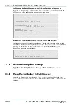
Page 90: ...00 TimeStamp Jan 28 2005 17 46 22 Press Enter to continue Software Update Menu Option 4 Reboot Modulator Select option 4 to reboot the Modulator This is only needed after a code download or after swi...

Page 91: ...ull Access Mode 4 6 4 2 4 Edit Mode 4 9 4 2 5 Change Parameter 4 9 4 2 6 Change Configuration 4 9 4 2 7 Example Setting the IP Address from the Front Panel 4 9 4 3 Configuration Options 4 10 List of F...

Page 92: ...Front Panel Control Page 4 2 Reference Guide SM6610 SM6615 SM6620 and SM6625 Satellite Modulators ST RE E10152 2 BLANK...

Page 93: ...tware options installed in it The options available in some front panel and terminal menus vary dependent upon the functionality available 4 1 2 Booting NOTE If necessary refer to Chapter 2 Installati...

Page 94: ...To change the selection use the arrow pushbuttons to scroll up and down Dash indicates current selection viewing only Data can be edited when enclosed in brackets Either toggle e g Enabled Disabled by...

Page 95: ...a snapshot of present alarms when Enter is pressed Logs Menu View Alarm Log History of alarms e g Input stream errors View Event Log History of events e g When Modulator was restarted When new config...

Page 96: ...he Modulator can be fully controlled giving the user full access with editing and viewing capabilities for all accessible menus In Full Access mode the Main Menu is as shown in Figure 4 4 NOTE In Full...

Page 97: ...imits dependent upon selected Packet Size Modulation and FEC Rate Symbol Rate 1 48 Msymbol s 0 2 66 Msymbol s with Extended Symbol Rate option Coding Mode DVB Modulation BPSK QPSK 8PSK 16QAM with HOM...

Page 98: ...previously stored configurations Save Configuration Allows current configurations to be stored in Flash memory Edit Config Name Allows the configuration names to be edited System Menu Network Setting...

Page 99: ...ion 4 2 6 Change Configuration To change the configuration a pending configuration is created by selectively modifying various parameters as required When all changes have been made select Quit The fo...

Page 100: ...hange To cancel the change press Cancel NOTE Erroneous address settings cannot be saved 4 3 Configuration Options Table 4 5 lists the options available Table 4 5 Configuration Options Configuration Se...

Page 101: ...5 3 5 Save Configuration 5 13 5 3 6 Get Version Information 5 13 General 5 13 Host Controller Card S11340 5 14 Modulator Baseband Card S13129 S13133 5 15 DVB ASI SPI Input Card S11341 5 15 5 4 Get Sta...

Page 102: ...otocol Page 5 2 Reference Guide SM6610 SM6615 SM6620 and SM6625 Satellite Modulators ST RE E10152 2 Table 5 22 Get Status 5 16 Table 5 23 Save Current Configuration 5 16 Table 5 24 Get Health 5 17 Tab...

Page 103: ...Chapter either via RS 232 or Ethernet RS 232 The rear panel connector is designated RS 232 485 This is configured to run between 300 and 38400 baud see Section 3 7 System Menu Option 4 Serial Port Con...

Page 104: ...example of a Message sent to the Modulator Table 5 2 Example Message Byte Value Description 1 0x2A 2 0x2A 3 0x05 The total length of the TLV section checksum 4 0x01 The type of the message 5 0x02 The...

Page 105: ...ed in it The validity of some parameter values in configuration messages to the Modulator is dependent upon the functionality available Parameter values are validated by the Modulator and accepted or...

Page 106: ...protocol version Size Value Protocol Version 0x00 0xFF See Section 5 8 Protocol Version 1 Input Select 0x00 SPI 0x01 ASI 1 0x02 Reserved 0x03 ASI 2 0x04 ASI 3 0x05 ASI 4 0x10 Test packets Null 0x11 T...

Page 107: ...Modulation On Off 0x00 Off 0x01 On 1 Reserved Set to 0x0000 2 Reserved Set to 0x00 1 IF Power Set IF power in 0 1 dB steps Byte 1 IF Power bits 15 8 Byte 2 IF Power bits 7 0 Value as signed 16 bit in...

Page 108: ...e Section 5 8 Protocol Version 1 Input Select 0x00 SPI 0x01 ASI 1 0x02 Reserved 0x03 ASI 2 0x04 ASI 3 0x05 ASI 4 0x10 Test packets Null 0x11 Test packets PRBS 1 Reserved Set to 0x00 1 Packet Size 0x00...

Page 109: ...x0000 2 Reserved Set to 0x00 1 IF Power Set IF power in 0 1 dB steps Byte 1 IF Power bits 15 8 Byte 2 IF Power bits 7 0 Value as signed 16 bit integer e g 0x000A 1 0 dBm 0xFFFF 0 1 dBm 2 IF Frequency...

Page 110: ...Information Type 0x76 Length 0 5 2 8 Get Status This message prompts the Modulator to return the current status Table 5 9 Get Status Type 0x77 Length 0 5 2 9 Save Current Configuration Saves the curre...

Page 111: ...tion Type 0x73 Length 1 Size Value Operation Success 0x00 Error 0x0F Invalid Parameter 1 Otherwise the Modulator configuration is returned Table 5 14 Upload Configuration Normal Condition Type 0x73 Le...

Page 112: ...nse 0x00 Normal 0x01 Inverted 1 Spectrum roll off factor Alpha 0x02 20 0x03 25 0x04 30 0x05 35 1 Modulation On Off 0x00 Off 0x01 On 1 Reserved Ignore value 2 Reserved Ignore value 1 IF Power Set IF po...

Page 113: ...cess 0x00 Error 0x01 OK 0x0F Invalid Parameter 1 5 3 5 Save Configuration Table 5 17 Save Configuration Type 0x81 Length 1 Size Value Operation Success 0x00 Error 0x01 OK 0x0F Invalid Parameter 1 5 3...

Page 114: ...g e g ASCII 01 2 Monitor Minor Version Number Text string e g ASCII 01 2 Web Site Version Number Text string with zero terminator e g ASCII 01 01 01 02 etc 6 Host Controller Card CPLD Firmware Version...

Page 115: ...l Software Version Upper nibble major version number Lower nibble minor version number 1 IF Card Type Text string e g ASCII 10310 11291 etc 5 IF Card PCB Revision and Modification Status Upper nibble...

Page 116: ...1 Bit 0 1 1 0 5 Reserved Default 0 6 Modulation Off On Modulator Status 7 Carrier on off Off On Symbol clock offset ppm Signed integer value MSB first 2 Temperature C Signed byte 1 Alarm Status Bit 0...

Page 117: ...Reserved Default 0 6 Critical Fail OK Fail Value Health word Assume 0x00 for normal operation 7 Reserved Default 0 5 7 Bad Message This message is sent in reply to a message that could not be process...

Page 118: ...RS 232 Remote Control Protocol Page 5 18 Reference Guide SM6610 SM6615 SM6620 and SM6625 Satellite Modulators ST RE E10152 2 BLANK...

Page 119: ...vate Configuration 6 13 6 4 2 Upload Configuration 6 13 6 4 3 Upload Current Configuration 6 14 6 4 4 Download Configuration 6 15 6 4 5 Save Configuration 6 15 6 5 Get Status 6 16 6 6 Save Current Con...

Page 120: ...RS 485 Remote Control Protocol Page 6 2 Reference Guide SM6610 SM6615 SM6620 and SM6625 Satellite Modulators ST RE E10152 2 BLANK...

Page 121: ...r is compatible with either RS 232 or RS 485 depending upon the mode selected on the Modulator The RS 485 mode can be configured to use one of several baud rates Other settings are 8 data bits no pari...

Page 122: ...e can be from 110 to 12710 inclusive This field is 1 byte in length type Specifies the type of command response message This field is numeric and 2 bytes in length with valid values value Is the comma...

Page 123: ...l data is added to a message it will be added at the end of the value field thus allowing software written for an earlier version of the message to still function Numeric Fields A numeric field consis...

Page 124: ...ype 0x73 Save Current Configuration Message type 0x80 Activate Stored Configuration Message type 0x71 Figure 6 1 SM66XX Remote Control Configurations can be stored in any of the 8 slots provided or ac...

Page 125: ...r s built in default configuration Table 6 3 Activate Configuration Parameters Size Type 0x71 2 Value Configuration Number 0x01 0x09 2 6 3 2 Upload Configuration Sending this message retrieves the spe...

Page 126: ...1 Test packets PRBS 2 Reserved Set to 0x00 2 Packet Size 0x00 204 byte 0x01 188 byte 2 Reserved Set to 0x00 2 Bit rate Set interface bit rate in 1 bit s increments This value is only used if Symbol ra...

Page 127: ...Reserved Set to 0x00 2 IF Power Set IF power in 0 1 dB steps Value as 16 bit signed integer e g 0x000A 1 0 dBm 0xFFFF 0 1 dBm 4 IF Frequency Set IF frequency in units of 1 kHz e g 70 MHz 0x011170 6 Ge...

Page 128: ...ASI 2 0x04 ASI 3 0x05 ASI 4 0x10 Test packets Null 0x11 Test packets PRBS 2 Reserved Set to 0x00 2 Packet Size 0x00 204 byte 0x01 188 byte 2 Reserved Set to 0x00 2 Bit rate Set interface bit rate in...

Page 129: ...ed Set to 0x0000 4 Reserved Set to 0x00 2 IF Power Set IF power in 0 1 dB steps Value as 16 bit signed integer e g 0x000A 1 0 dBm 0xFFFF 0 1 dBm 4 IF Frequency Set IF frequency in units of 1 kHz e g 7...

Page 130: ...r to return the current status Table 6 8 Get Status Size Type 0x77 2 6 3 7 Save Current Configuration Saves the current configuration to a specified configuration slot Table 6 9 Save Current Configura...

Page 131: ...ulator processed the outgoing message the following response will occur The start field for this message is NAK Table 6 12 Upload Configuration Error Condition Size Type 0x73 2 Value Operation Success...

Page 132: ...pha 0x02 20 0x03 25 0x04 30 0x05 35 2 Modulation On Off 0x00 Off 0x01 On 2 Reserved Ignore value 4 Reserved Ignore value 2 IF Power IF power in 0 1 dB steps Value as 16 bit signed integer e g 0x000A 1...

Page 133: ...Configuration The start field for this message is ACK if OK is indicated otherwise the start field is NAK Table 6 15 Download Configuration Size Type 0x70 2 Value Operation Success 0x00 Error 0x01 OK...

Page 134: ...Off Off On 2 Symbol clock offset ppm Signed integer value MSB first 4 Temperature C Signed byte 2 Bit 0 1 0 Reserved Ignore value 1 Alarm 1 OK Set 2 Alarm 2 OK Set 3 Alarm 3 OK Set 4 Alarm 4 OK Set 5...

Page 135: ...RE E10152 2 6 7 Get Health The start field for this message is ACK Table 6 19 Get Health Size Type 0x79 2 Bit 0 1 0 5 Reserved Ignore value 6 Critical Fail OK FAIL Value Health word Assume 0x00 for n...

Page 136: ...RS 485 Remote Control Protocol Page 6 18 Reference Guide SM6610 SM6615 SM6620 and SM6625 Satellite Modulators ST RE E10152 2 BLANK...

Page 137: ...Interface 7 5 Transport Stream Rate Adaptation 7 5 Transport Stream De jittering 7 6 DVB Encoding 7 6 PREKOR Dynamic Pre correction S13133 Card Only 7 6 7 3 3 Output Card 7 6 S10310 IF Output Card 7...

Page 138: ...Equipment Description Page 7 2 Reference Guide SM6610 SM6615 SM6620 and SM6625 Satellite Modulators ST RE E10152 2 BLANK...

Page 139: ...gged with respect to noise and interference Five convolutional code rates are available with BPSK and QPSK modulations as follows 1 2 2 3 3 4 5 6 and 7 8 These provide different compromises between bi...

Page 140: ...bi decoded de interleaved and then RS decoded The inner convolutional coding together with Viterbi decoding provides powerful error correction capability against errors induced by additive white Gauss...

Page 141: ...he data to be transmitted The Modulator can be made to switch if the input in use suffers a failure although automatic switching is not currently supported The Baseband card can accept transport strea...

Page 142: ...y adjusting the level of pre correction in response to an input voltage derived from an external satellite beacon receiver This facility is useful for compensating for uplink fades when using PREKOR w...

Page 143: ...ompliant MPEG 2 transport streams via either the Synchronous Parallel Interface SPI or the two Asynchronous Serial Interfaces ASI The user can connect a stream into any of the three interfaces It is a...

Page 144: ...ata bytes being transmitted and then a series of K28 5 code words until the next packet of data is ready to be transmitted Figure 7 3 Functional Block Diagram IF Output Models SM6610 and SM6620 Analog...

Page 145: ...t Main I Q Modulator Synthesiser Amplifier and Gain Control L Band Output Card S11291 L Band Out Monitor L Band In I Q Analogue I Q Baseband Card S13129 S13133 FIFO Buffer Microprocessor DVB Encoding...

Page 146: ...Equipment Description Page 7 10 Reference Guide SM6610 SM6615 SM6620 and SM6625 Satellite Modulators ST RE E10152 2 BLANK...

Page 147: ...Overheating 8 8 8 8 VT100 Terminal Emulation Program Problems 8 9 8 9 Alarm and Failure Reporting 8 9 8 9 1 Introduction 8 9 8 9 2 Alarm Severity Levels 8 9 8 9 3 Alarm Groups 8 10 8 9 4 Host Controll...

Page 148: ...Preventive Maintenance and Fault finding Page 8 2 Reference Guide SM6610 SM6615 SM6620 and SM6625 Satellite Modulators ST RE E10152 2 BLANK...

Page 149: ...nvironment in which it is going to be used 8 2 2 Cleaning Unplug the equipment from the supply before cleaning Do not use liquid or aerosol cleaners Use a damp cloth for cleaning the exterior of the M...

Page 150: ...s It has a large team dedicated to keeping our customers on air 24 hours a day 365 days a year With regional offices worldwide and ultra modern specialist service facilities in the US UK Hong Kong and...

Page 151: ...y prior to taking remedial action Fault diagnosis for the equipment operator is limited to the following tasks since the operator should NOT remove the covers of the equipment 1 Check the front panel...

Page 152: ...1 Not Fitted Software Options SM66XX SWO HS Extended Symbol Rate SM66XX SWO HOM Higher Order Modulations Figure 8 1 Example Boot Display NOTE The boot display indicates the software version number the...

Page 153: ...t i e Encoder etc configured incorrectly Configure the Modulator and MPEG 2 data source equipment correctly paying particular attention to the Input Data Selection ASI1 etc Packet Size Bit rate Symbol...

Page 154: ...it in another piece of equipment Does it work The problems lies within the Modulator Proceed to next step The problem lies either with the cable itself or with the fuse in the plug Replace the fuse or...

Page 155: ...one or more previously reported alarms This alarm clears all alarms for the Modulator that have the same alarm type probable cause and specific problems if given 2 The indeterminate severity level ind...

Page 156: ...roller Card Alarms Terminal Alarm Message Front Panel Alarm Message Severity Level Booting Booting Critical Test Mode Test Mode Critical No Baseband Card No Baseband Card Critical No IF Card No IF Car...

Page 157: ...ssage Severity Level Hardware Fail Hardware Fail Critical FPGA Configuration Fail FPGA Config Fail Critical FPGA Temperature High FPGA Temp High Critical FPGA Clock Unlocked FPGA Clock Unlocked Critic...

Page 158: ...rm Message Severity Level IF Carrier Frequency Unlocked IF Carrier Frequency Unlocked Critical IF Output Muted IF Output Muted Critical Up converter Power Shutdown UpConv Power Shutdown Major 8 9 8 Fr...

Page 159: ...ogged In A user logged in via FTP Logs Reset Flat Battery The logs have been reset due to the battery being flat Modulator Stopped Net Config Changed The network parameters were changed New Configurat...

Page 160: ...Preventive Maintenance and Fault finding Page 8 14 Reference Guide SM6610 SM6615 SM6620 and SM6625 Satellite Modulators ST RE E10152 2 BLANK...

Page 161: ...Logs Directory 9 5 9 1 6 The Config Directory 9 6 Contents of the Directory 9 6 Typical Config Files 9 7 Downloading Configurations 9 8 Exiting FTP Session 9 8 9 1 7 Connecting to a Web Browser 9 9 9...

Page 162: ...File Transfer Protocol FTP Page 9 2 Reference Guide SM6610 SM6615 SM6620 and SM6625 Satellite Modulators ST RE E10152 2 BLANK...

Page 163: ...ver However it should be noted that the Modulator will only allow one logon at a time and many graphical FTP clients use multiple logons The sample screens given in this chapter were obtained using th...

Page 164: ...file 9 1 3 The Software Directory This directory contains the software for the Modulator To enter the software directory type cd software ftp cd software 250 software ftp dir 200 Set port to 172 17 2...

Page 165: ...e Modulator Baseband Card 9 1 5 The Logs Directory This directory contains the logs kept by the Modulator These are the same logs as those viewed on the terminal described in Chapter 3 Operating the E...

Page 166: ...et cfg nor the version cfg files can be deleted All other configuration files can be deleted ftp cd config 250 config ftp dir 200 Set port to 172 17 225 20 1166 150 opening data connection r r r 1 Any...

Page 167: ...it rate 30 000000 Mbit s Symbol Rate 20 000000 Msym s Coding Mode DVB Modulation Format QPSK FEC Rate 3 4 Roll off 35 IF Frequency 70 000 MHz IF Power 4 0 dBm IF Output ON Mod State ON Spectrum Sense...

Page 168: ...00000000 CPLD Firmware Version 1 0 DSP Firmware Version 2 0 Software Version 2 0 Modulator IF Card Card Type S10310 PCB Revision 3 Modification Status 0 Serial No 0008003940E2 Firmware Version 1 1 Sof...

Page 169: ...h your user name password with your password and IP Address with the address of the Modulator For example the following address will connect the root user to a Modulator on address 192 168 55 3 ftp ro...

Page 170: ...lick on the file This will display a download confirmation window as shown in Figure 9 2 Figure 9 2 Typical File Download Screen Click OK to continue with the download You will then be asked to select...

Page 171: ...te Modulators Page 10 1 ST RE E10152 2 Chapter 10 10 Licence Keys Contents 10 1 Introduction 10 3 10 2 Obtaining Licence Keys 10 3 10 3 Entering Single Licence Keys 10 4 10 3 1 Single Key 10 4 10 3 2...

Page 172: ...Licence Keys Page 10 2 Reference Guide SM6610 SM6615 SM6620 and SM6625 Satellite Modulators ST RE E10152 2 BLANK...

Page 173: ...rs of the Modulators These can be obtained from the Terminal or FTP interfaces Below is a typical version information screen from the terminal Identifying Name DEV001 Unit Inventory Serial No 1 Unit I...

Page 174: ...Password required for user root Password 230 Modulator identity 230 DEV001 230 User logged in ftp cd keys 250 keys ftp put licence dat 200 Set port to 172 17 225 20 1356 150 opening data connection 22...

Page 175: ...ve Differential Pulse Code Modulation An advanced PCM technique that reduces the bit rate by coding the difference values between successive samples rather than the absolute value of each sample ADT A...

Page 176: ...hest frequencies transmitted High bandwidth allows fast transmission or high volume transmission Byte mode Each byte is delivered separately in the ASI Transport Stream with stuffing data added betwee...

Page 177: ...spectrum analyser Can be forward DCT or inverse DCT DDS Direct Digital Synthesiser Decoder The unit containing the electronic circuitry necessary to decode encrypted signals Some Decoders are separat...

Page 178: ...ect any errors FFT Fast Fourier Transformation A fast algorithm for performing a discrete Fourier transform FIFO First In First Out A data structure or hardware buffer from which items are taken out i...

Page 179: ...al ISDN Integrated Services Digital Network The basic ISDN service is BRI Basic Rate Interface which is made up of two 64 kbit s B channels and one 16 kbit s D channel 2B D If both channels are combin...

Page 180: ...DVD etc and transmissions up to 15 Mbit s over various mediums MP HL Main Profile at High Level A subset of the MPEG 2 standard which supports digital video storage DVD etc and transmissions up to 80...

Page 181: ...range from dark to light a scale of 0 255 for an eight bit pixel Colour systems use a red green and blue dot per pixel each of which is energised to different intensities creating a range of colours...

Page 182: ...thorized viewing of a TV programme or programmes RF Radio Frequency ROM Read Only Memory A non volatile storage device for digital data Data has been stored permanently in this device No further infor...

Page 183: ...k Management Protocol Spatial Redundancy Information repetition due to areas of similar luminance and or chrominance characteristics within a single frame Removed using DCT and Quantisation Intra Fram...

Page 184: ...ed for the disk is temporarily stored in RAM and can be lost in the event of a power failure Sophisticated systems are tied to electrical generators that can provide power for days UPS systems typical...

Page 185: ...ompliance B 13 B 11 1 Safety B 13 B 11 2 EMC B 13 B 11 3 CE Marking B 14 B 11 4 C Tick Mark B 14 B 12 Cable Types B 14 List of Tables Table B 1 RS 232 RS 485 Control Specification B 3 Table B 2 Ethern...

Page 186: ...Technical Specification Page B 2 Reference Guide SM6610 SM6615 SM6620 and SM6625 Satellite Modulators ST RE E10152 2 BLANK...

Page 187: ...impedance 100 RS 485 inputs only Supported Baud rates 300 600 1200 2400 4800 9600 19200 default 38400 Baud Data bits 8 Parity None Stop bits 1 Flow control None Control modes Terminal remote Local con...

Page 188: ...ts DVB ASI IN All Base Unit Models Two DVB ASI electrical inputs are provided as standard on each Modulator Base Unit model One of the two inputs is selected under user control as the input to the Mod...

Page 189: ...00 8PSK 8 9 2 457516 117 960784 2 666667 128 000000 3 4 2 764706 132 705882 3 000000 144 000000 16QAM 7 8 3 225490 154 823529 3 500000 168 000000 Table B 6 Input Bit rate Ranges Extended Symbol Rate O...

Page 190: ...MAIN Specification Item Specification Safety status SELV Connector type BNC female 75 Connector designation IF OUT MAIN Output impedance 75 Output power 20 dBm to 5 dBm in 0 1 dB steps Power level sta...

Page 191: ...hase noise continuous 66 dBc Hz at 100 Hz offset 76 dBc Hz at 1 kHz offset 86 dBc Hz at 10 kHz offset 96 dBc Hz at 100 kHz offset 120 dBc Hz at 1 MHz offset and above Phase noise discrete sidebands 70...

Page 192: ...ion L BAND IN Input impedance 50 Gain to L BAND OUT MAIN output 0 dB 2 dB Input power 5 dBm max Return loss 14 dB 950 1750 MHz B 5 2 L Band Outputs Table B 11 L BAND OUT MAIN Specification Item Specif...

Page 193: ...pectrum sense Normal inverted Transmission modes Modulation on off Carrier on off Carrier frequency 950 1750 MHz tuneable in 1 kHz steps Carrier frequency error 35 Hz versus temperature 1 kHz ageing o...

Page 194: ...put Specification Item Specification Output power 0 dBm 3 dB sine wave into 50 load Switchable on off Frequency 10 MHz Frequency stability 0 2 Hz versus temperature 1 Hz ageing over 1 year 5 5 Hz agei...

Page 195: ...range Defined by symbol rate range modulation format FEC code rate and input packet size as per Table B 5 Input Bit rate Ranges Standard and Table B 6 Input Bit rate Ranges Extended Symbol Rate Optio...

Page 196: ...ect mains polarity must always be observed Do not use reversible plugs with this equipment Class of equipment Class I Equipment EN 60950 para 1 2 4 electric shock protection by basic insulation and pr...

Page 197: ...een designed and tested to meet the requirements of the following EN 60950 European Safety of information technology equipment IEC 60950 International Safety of information technology equipment In add...

Page 198: ...EEC of 3 May 1989 on the approximation of the laws of the Member States relating to electromagnetic compatibility 73 23 EEC of 19 February 1973 on the harmonisation of the laws of the Member States re...

Page 199: ...Suitable Signal Cable Types Signal Type Connector Cable RS 232 9 way D type Male Belden 8162 CM 2PR24 shielded E108998 typical Ethernet RJ 45 Alcatel Data Cable FTP 7 x 0 16 ASI Inputs BNC Canford Aud...

Page 200: ...Technical Specification Page B 16 Reference Guide SM6610 SM6615 SM6620 and SM6625 Satellite Modulators ST RE E10152 2 BLANK...

Reviews: