RS-485 Remote Control Protocol
Reference Guide: SM6610, SM6615, SM6620 and SM6625 Satellite Modulators
Page 6-3
ST.RE.E10152.2
6.1 Introduction
6.1.1
Read This First!
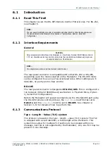
This chapter covers the RS-485 Remote Control Protocol only. For RS-232,
see Chapter 5.
NOTE…
The rear panel RS-232/485 connector is compatible with either RS-232 or RS-485, depending upon
the mode selected on the Modulator. (See Section 3.7 System Menu, Option 4, Serial Port
Configuration.)
6.1.2 Interface
Requirements
General
CAUTION…
Only one logical control interface on the Modulator, i.e. Front Panel, Terminal, SNMP Remote Control,
FTP, etc, should be used at any one time. Using more than one interface simultaneously may cause
unexpected behaviour of the Modulator.
NOTE…
This chapter covers Version 4 of the Remote Control Protocol.
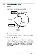
The rear panel connector is compatible with either RS-232 or RS-485,
depending upon the mode selected on the Modulator. The RS-485 mode
can be configured to use one of several baud rates. Other settings are 8
data bits, no parity and no flow control.
RS-485
The rear panel connector is designated RS-232/485. This is configured to
run between 300 and 38400 baud (see Section 3.7 System Menu, Option
4, Serial Port Configuration).
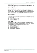
Before the Modulator will accept commands via the RS-232/485 port using
the RS-485 remote control protocol, the
Port Mode
must first be set to
Remote and the
Interface
must be set to RS-485. See Chapter 3,
Section 3.7.2 for details of how to perform this.
6.1.3 Communications
Protocol
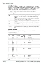
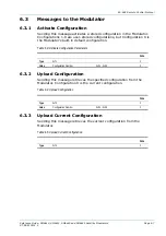
Type - Length - Value (TLV) system
The protocol is based on the type - length - value (TLV) system. This TLV
is wrapped with a start identifier, a total length and a checksum. This
system does allow for multiple TLV sections to be included within one
message, but this is not supported by the Modulator; only one TLV may be
present in one message.

