


90
VISION 5000 Videoconferencing System
Appendix 2
The cable set consists of a pair of RS-366/V.35 cables cable and should be connected thus:
Configuration of Vision 5000
Press
MENU
on the remote control. Select Terminal Settings.
Select Current Network: External and check the following:
==== External Network Settings ====
Call Control:
RS366 Dialling
Leased Line
Data Triggered
Manual
Network Clocking:
RS449/V35 Compatible
X21 Compatible
Advanced Network Settings
Previous Menu
==== Advanced Network Settings ====
IMUX Default Prefix, Net1: _____
IMUX Default Prefix, Net2: _____
IMUX Restrict Offset: ___
Previous Menu
Clear the IMUX Default Prefix, Net1, IMUX Default Prefix, Net2 and IMUX Restrict Offset.
If the CSUs are connected and configured properly (see next page), you are now ready to make your videoconferencing calls.
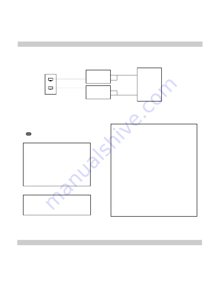
Net 1
Net 2
RS-366
V.35
RS-366
V.35
RS-366
VISION
CSU’s
Wall Socket
Circuit #1
Circuit # 2
Master Vision 6000
Using CSU/DSUs
Connect the RS366/V35 cable to NET 1 and CSU#1
Connect the RS366/V35 cable to NET 2 and CSU#2 .
Vision 5000
V.35/RS-366 cable
Signal Name
Female
Male 34pin
Male 25pin
44pin DSUB Winchester
DSUB
Frame ground
1
A
Signal ground
15,25,28,44
B
TX(A), transmit data 29
P
TX(B)
30
S
RX(A), receive data
40
R
RX(B)
39
T
RCLK(A), rcv clock
37
V
RCLK(B)
38
X
TCLK(A), xmt clock 41
Y
TCLK(B)
42
AA
DTR
7
H, C
RI
43
L, J
RLSD
36
F
DSR
6
E
RS366 DPR
9
2
RS366 ACR
10
3
RS366 CRQ
11
4
RS366 PND
12
5
RS366 DLO
13
22
RS366 NB1
21
14
RS366 NB2
22
15
RS366 NB4
23
16
RS366 NB8
24
17
RS366 DSC
14
13
RS366 GND
35
7


