TC36.NG03.C 010408-16
11
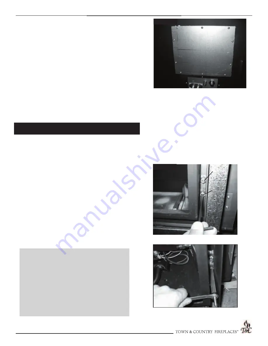
Fig. # 28
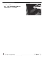
Fig. # 27
Fig. # 26
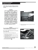
1)
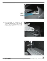
Remove the plug from the pressure test port. The plug is
located between the right side lintel and fi rebox side. (Fig.
# 27)
2)
Thread the extension test fi tting into the open test port.
(Fig. # 28)
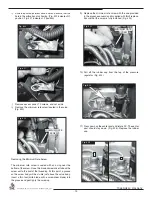
3)
Attach a pressure gauge onto the fi tting
4)
When testing is complete remove the extension piece and
replace the pipe plug. Thread sealant will be required to
ensure a gas tight connection.
Note: To test the gas pressure, turn off the gas supply before
removing the blanking plug from the supply pressure test
port or manifold pressure test port.
Verify gas pressures with the fi replace lit and on the
highest setting.
12) Fill in the date and the name of the person who performed the
conversion in the white area on the conversion label. Peel off
the protective backing and apply the conversion label directly
over the gas specifi cations on the rating label.
13) Attach the access panel to the side of the fi rebox with the
previously removed screws. (Fig. #26)
Note: Gasket must be installed with access panel.
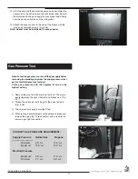
CORRECT GAS PRESSURE REQUIREMENT:
Supply Pressure
Natural Gas
Propane
Minimum
5.0” wc
12.5” wc
Maximum
13.9” wc
13.9” wc
Manifold Pressure
Maximum
3.8” wc
11.0” wc
Minimum
2.1” wc
5.5” wc
(For purpose of input adjustment)
Gas Pressure Test
SUPPLY
SUPPLY
MANIFOLD
MANIFOLD
Summary of Contents for TC36.NG03.C.
Page 14: ...TC36 NG03 C 010408 16 14 NOTES ...


