background image

page 16      TC42_B2 

230905-36

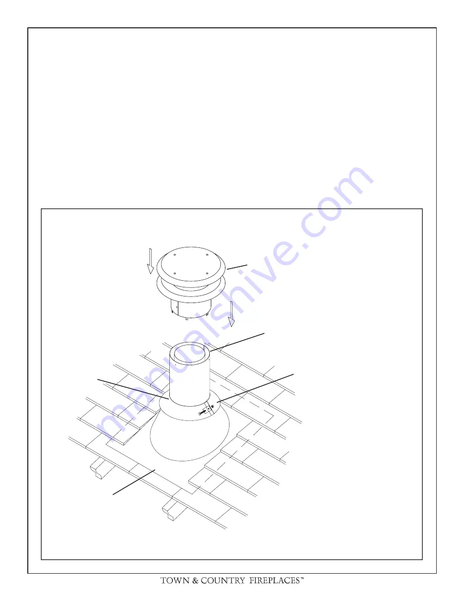
Fig. # 21

VERTICAL TERMINATION CAP

(TCVT.9365)

FLASHING

STORM COLLAR

(TC42.90665)

MASTIC

Note:  Adjustable for various 
roof pitches, from fl at roof to 
12/12 pitch roof.

VENT PIPE

Roof vent terminal:

1)  Place the roof fl ashing over top of the vent pipe and nail 

securely to the roof using roofi ng nails, top and sides 
U

N

DER shingles, lower end OVER shingles to provide 

a watershed. Make weather tight by sealing with roofi ng 
compound (see Fig. #21).

2)  Place the storm collar down over the vent pipe until it 

is level. Tighten storm collar for a snug fi t. Apply a thick 
horizontal ring of mastic around the pipe at top of storm 
collar (see Fig. #21).

3)  Lower the roof vent terminal cap over the vent pipe and 

secure in place with screws provided (see Fig. #21). Seal 
screw heads and joint with caulking to prevent any moisture 
entering the venting system.

Summary of Contents for TC42 B Series

Page 1: ...Follow the gas supplier s instructions Ifyoucannotreachyourgassupplier call the fire department Installationandservicemustbeperformed by a qualified installer service agency or the gas supplier FOR YO...

Page 2: ...LL SWITCH 20 OR THERMOSTAT Canada Only 20 WINDOW FRAME REMOVAL 21 BRICK PANELS INSTALLATION 22 FIRST FIRE 23 OPERATING 23 LIGHTING INSTRUCTIONS Millivolt Valve 23 LIGHTING INSTRUCTIONS Electronic Valv...

Page 3: ...as been under water Immediately call a qualified service technician to inspect the fireplace and to replace any part of the control system and any gas control which has been under water SAFETY Due to...

Page 4: ...4 in 45 mm Horizontal vent pipe Top 1 3 4 in 45 mm Sides 1 3 4 in 45 mm Bottom 1 3 4 in 45 mm Fig 3 CEILING ADJACENT WALL OR MANTEL SUPPORT M A N T E L UNIT MAY BE RECESSED UP TO 6 WITH NON COMBUSTIB...

Page 5: ...4 Assembly 1 Remove the standoffs from inside the fireplace 2 Position the standoffs in place and secure with screws provided LOCATING THE FIREPLACE In planning the installation for the fireplace it...

Page 6: ...teel frame to the framing brackets on each side of the unit Ensure that the studs are set back far enough to allow for thickness of finishing surface The sides back and top of the fireplace can be fra...

Page 7: ...control box placement and vent installation Fireplace should be in its final location before framing 6 CONCRETE BOARD STEEL STUDS NON COMBUSTIBLE M A S O N R Y T Y P E MATERIAL Fig 8 CAUTION When fram...

Page 8: ...to the firebox CONTROL BOX FRAMING Caution When positioning the control box do not over bend the conduit or use excessive force as damage may occur 1 Remove window frame latch tool and set aside 2 Re...

Page 9: ...asonry wall allow for control door and frame removal If flush mounted on a masonry wall allow for conduit to exit out the bottom of control box C a u t i o n W h e n positioning the control box do not...

Page 10: ...n towards the termination HEARTH EXTENSION While a hearth extension is not required for this fireplace one is recommended for aesthetic reasons The hearth extension should be noncombustible and must n...

Page 11: ...shing Flat TCVT 811FLFLT Roof Flashing Steep TCVT 811FLSTP or any that fits 11 pipe Fig 15 WALL THIMBLE AND VENT MUST NOT PROTRUDE BEYOND SIDING Fig 14 Fig 15a TRIM TO LENGTH Wall thimble Where a vent...

Page 12: ...rovided The fireplace position may need to be adjusted to ensure that the vent pipe does not protrudes beyond the outer wall or be recessed any more than 12 inches Wall vent terminal 1 Engage the 8 ve...

Page 13: ...this chart A total of 3 90 elbows or combina tion of other elbows equalling 90 can be used without reducing horizontal run For each additional 90 elbow or an equal com bination of elbows reduce horizo...

Page 14: ...4 90 elbows or combina tion of other elbows equalling 90 can be used without reducing horizontal run For each additional 90 elbow or an equal com bination of elbows reduce horizontal vent run by 2 fe...

Page 15: ...om the vent pipe Additionally after the vent pipe is in place install a storm collar on top of the shield This will prevent loose insulation from falling into the area between the vent pipe and the sh...

Page 16: ...and sides UNDER shingles lower end OVER shingles to provide a watershed Make weather tight by sealing with roofing compound see Fig 21 2 Place the storm collar down over the vent pipe until it is lev...

Page 17: ...eter regulator assembly within 3 feet 90 cm horizontally from the center line of the regula tor I clearance to service regulator vent outlet 6 feet 1 8 m minimum J clearance to nonmechanical air suppl...

Page 18: ...supplied with the appliance All outer joints of the vent pipe must be sealed with the ap proved High Temp self adhesive aluminum tape provided Wrap the tape completely around the joint and press firm...

Page 19: ...sition is too closed if the flame has the following characteristics Flame is excessively tall and lifting Flame lacks movement Flame soots Restrictor position is too open if the flame has the followin...

Page 20: ...ILE OPTIONAL WALL SWITCH INLET PRESSURE TEST POINT MANIFOLD PRESSURE TEST POINT PILOT FLAME ADJUSTMENT SCREW BURNER ROCKER SWITCH OR OR GAS VALVE OPTIONAL WALL SWITCH OR THERMOSTAT Canada Only Note Us...

Page 21: ...atches and are operated by a removable handle The handle is located in the Control Box 1 Insert the latch handle onto the catch located 6 down from the top corners Rotate up to disengage each of the t...

Page 22: ...nstall the Left Side Panel by inserting the bottom of the panel in first and then angling it up into position It may be necessary to push the upper firebox shield up to allow panel to move freely into...

Page 23: ...he pilot will not stay lit after several tries turn the gas control knob to Off and call your service technician or gas supplier 9 Turn gas control knob counter clockwise to On posi tion 10 Turn HI LO...

Page 24: ...to light the pilot by hand B BEFORE LIGHTING smell all around the appliance area for gas Be sure to smell next to the oor because some gas is heavier than air and will settle on the oor WHAT TO DO IF...

Page 25: ...of glass with the gasket into the frame so that the thicker bead of gasket faces the fireplace PILOT FLAME FLAME SENSOR ELECTRODE Fig 32 MILLIVOLT PILOT ELECTRONIC PILOT Annual Inspection a Remove gl...

Page 26: ...LEFT SIDE TUSCAN 5098 5473 B PANEL LT SIDE HERITAGE RED 5098 552 2 B 10 PANEL LEFT BASE BRICK 5098 545 PANEL LEFT BASE TUSCAN 5098 54015 PANEL LT BASE HERITAGE RED 5098 552 5 11 PANEL LWR BACK HERRING...

Page 27: ...12 CONTROL BOX BRACKET 9075 13 BURNER SWITCH WIRE ASSEM OXFD 50625 14 VALVE ASSEM NG c w sp cable TC42 5007 15 SPARKER CABLE 5016 901 16 MINIMUM INPUT STOP 9076 001 17 PILOT FLAME DISPLAY ASSEM TC42 5...

Page 28: ...CTRONIC WIRE HARNESS 5030 05 A 6 ELECTRONIC KNOB EXTENSION 5030 06 7 VALVE BRACKET BOTTOM 9078 8 VALVE BRACKET TOP 9078 5 9 TRANSFORMER BRACKET 9079 5 All other replacement parts are the same as the p...

Page 29: ...Pilot Assembly Ignition Module Pilot Gas Line B l a c k through independent conduit Black S through Gas line conduit AC Adaptor Battery Relay Black Red Black Wire Harness Note Wire tags are bracketed...

Page 30: ...30 TC42_B2 230905 36 16 1 2 16 1 2 9 5 8 WALL TERMINATION KIT TCVT WTA Fig 38 WALL TERMINAL TCVT 9360 WALLSHIELD CEILING FIRESTOP THIMBLE TCVT THIMA WALL SHIELD CEILING FIRESTOP THIMBLE TCVT THIMA Fi...

Page 31: ...230905 36 TC42_B2 page 31 16 1 2 9 ROOF TERMINATION KIT TCVT RTA Fig 40 ROOF SUPPORT BRACKET TCVT 93915 CEILING FIRESTOP TCVT THIMA STORM COLLAR TC42 90665 VERTICAL TERMINATION CAP TCVT 9365...

Page 32: ...T PIPE DIMENSIONS Fig 41 4 5 11 9 1 2 10 15 16 10 5 16 15 7 8 7 16 1 5 16 8 5 16 13 13 16 12 9 16 13 1 8 11 1 8 TCVT 811X12ADJ TCVT 811XLB45 TCVT 811XLB90 TCVT 811X _ _ 12 Pipe 10 1 4 18 Pipe 16 1 4 2...

Page 33: ...20 B A C 1 1 4 B A C 1 1 4 B A 1 1 4 20 A B C 12 Pipe 18 5 8 18 18 Pipe 22 7 8 22 3 8 24 Pipe 27 1 8 26 1 2 48 Pipe 44 1 16 43 1 2 VENT OFFSET CHART Fig 42 11 3 8 10 7 8 1 1 4 Adding an adjustable se...

Page 34: ...ON PIPE WITH UNION COPPER LINE WITH FLARE FITTING GASTITETM FLEX LINE WITH REDUCING COUPLING Fig 43 Fig 44 Fig 45 Fig 46 Copper piping may only be used in compliance with local codes or in the absence...

Page 35: ...AIRANCES MINIMALES AVEC LES COMBUSTIBLE Left and Right side are determined when facing the front of the appliance Les c t s droit et gauche se d terminent en se mettant devant l appareil et en lui fai...

Page 36: ...2975 Allenby Rd Duncan B C V9L 4T8 Phone 1 888 223 0088 Web site www townandcountryfireplaces net Printed in Canada...

Reviews: