background image

Getting Ready

27

Re-installing the USB Device Driver

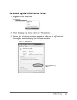
1.  Right click on the icon.

2.  From the pop-up menu click on "Properties" .

3.  When the following window appears, click on the [Reinstall 

Driver] button to display the Wizard window.

[General] Tab Window

[Reinstall Driver] 

Button

Summary of Contents for RTR-500AW

Page 1: ...1st Edition Introductory Manual Thank you for purchasing our product This manual explains in brief how to get an RTR 500NW 500AW unit ready for use and how to install the software Details about how to...

Page 2: ......

Page 3: ...nglish Website for your convenience Here you can nd information about our company news products upcoming events software and Introductory Manual downloads as well as other support Please stop by and s...

Page 4: ...Customers wishing to submit a defective product for repair or replacement during the warranty period should rst contact the dealer from whom it was originally purchased After receiving a return autho...

Page 5: ...nstalling the USB Device Driver 24 Checking the USB Device Driver 25 Re installing the USB Device Driver 27 Registering Device and Making Settings About Applications and the Operation Guide 32 How to...

Page 6: ...ts are subject to change without notice On screen messages in this manual may vary slightly from the actual messages Please notify the shop where you purchased this product or T D Corporation of any m...

Page 7: ...er direct or indirect from the inability to use RTR 500W for Windows T D Corporation has no obligation to correct any defects found in RTR 500W for Windows Copyright The Copyright for RTR 500W for Win...

Page 8: ...understand the contents Explanation of Symbols Explanation of Warning Symbols DANGER These entries are actions that absolutely under no circumstance should be taken The taking of such an action may c...

Page 9: ...from playing with or swallowing parts Do not connect any communication cables connected to the Unit to telephone line outlets Continued use may cause re or electrocution If any smoke or strange smells...

Page 10: ...ment whether directly or indirectly Harmful gases or chemicals may cause corrosion and or other danger to the Unit Also coming in contact with hazardous substances may cause harm to people handling th...

Page 11: ...Unit in the following places This may cause electrocution re and or other adverse effects to the Unit and or other surrounding devices Areas exposed to direct sunlight This will cause the inside of th...

Page 12: ...nd other devices which emit noise Keep all wires as far away from wireless communication devices as possible Please be careful about placing near any wiring or cables such as power supply cables telep...

Page 13: ...n be determined by turning the equipment off and on the user is encouraged to try to correct the interference by one or more of the following measures Reorient or relocate the receiving antenna Increa...

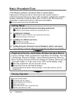
Page 14: ...carry out wireless communication with our RTR 500 Series Data Loggers E mail FTP T D Data Logging System RTR 500NW RTR 500AW Wired LAN Wireless LAN LAN Network T D Webstorage service Save Recorded Dat...

Page 15: ...ing Current Readings and Viewing Recorded Data via Web Browser By sending recorded data or current readings to the T D WebStorage Service it is possible to check and share data via a web browser T D W...

Page 16: ...Data Logger designed to measure and record temperature and humidity The wireless communication range between a Remote Unit and a Base Unit if unobstructed and direct is about 150 meters 500 ft Wireles...

Page 17: ...ed to a Base Unit It is possible to register them into Groups by place or by purpose A Wireless Communication Frequency Channel is then assigned to each Group to help avoid interference and poor trans...

Page 18: ...on Procedure Checking the USB Device Driver 4 Getting Ready the Remote Units and Repeaters where necessary Follow directions in the User s Manual that accompanies the Remote Unit or Repeater Registeri...

Page 19: ...6 Connect the Antenna 16 Appearance Diagram and Part Names 17 Installing the Software 19 Before Installing the Software 19 Procedure for Installing the Software 20 Installing the USB Device Driver 23...

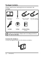
Page 20: ...enna USB Communication Cable US 15C LAN Cable LN 20W Only use for RTR 500NW AC Adaptor AD 0605 Software CD ROM Introductory Manual This Manual including warranty Make sure to install the software befo...

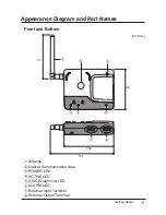
Page 21: ...y 17 Appearance Diagram and Part Names Front and Bottom 91 102 131 83 Unit mm Antenna Optical Communication Area POWER LED ACTIVE LED DIAG Diagnosis LED ALARM LED External Input Terminal External Outp...

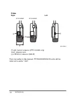
Page 22: ...18 Sides Right Left 28 RTR 500NW RTR 500AW Unit mm LAN Cable Connector RTR 500NW only AC Adaptor Jack USB Mini Connector Mini B From hereafter in this manual RTR 500NW 500AW units will be referred to...

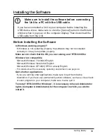
Page 23: ...tly or it may not operate properly Make sure to check that the OS you are running and RTR 500W for Windows are compatible Microsoft Windows 7 32 64bit English Microsoft Windows Vista 32bit English Mic...

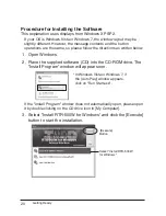
Page 24: ...s as written below 1 Open Windows 2 Place the supplied software CD into the CD ROM drive The Install Program window will appear soon In Windows Vista or Windows 7 if the Auto Play window appears click...

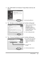
Page 25: ...l appear Please read all the terms stipulated in the agreement Check I accept the terms of the license agreement if you accept the terms Click the Next button 6 The Choose Destination Location window...

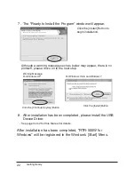
Page 26: ...oblem please move on to the next step Warning Message For Windows XP Click the Continue Anyway Button For Windows Vista and Windows 7 Click the Install Button 8 After installation has been completed p...

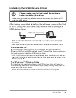
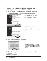
Page 27: ...Administrator Computer Administrator rights For Windows XP By connecting a data logger to your computer the New Hardware Detection Wizard will automatically open Please follow the procedure on the ne...

Page 28: ...tection Wizard will automatically open Check No not this time Click the Next Button Check Install the software automatically Recommended Click the Next Button 2 The installation process will begin If...

Page 29: ...e USB Device Driver 1 Open the Device Manager window Procedure example The screen shots below are from Windows XP SP2 In the Windows Start Menu click on Control Panel to open Click on Performance and...

Page 30: ...the Device Manager window in order to check whether or not the USB device driver has been properly installed If failed example If successful example If the icon appears with an or an the PC is not pr...

Page 31: ...e USB Device Driver 1 Right click on the icon 2 From the pop up menu click on Properties 3 When the following window appears click on the Reinstall Driver button to display the Wizard window General T...

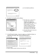
Page 32: ...n to step 6 Check the Install from a list or speci c location Advanced Click the Next Button Check the Include this location in the search Click the Browse Button 5 If you are using Windows Vista or W...

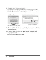
Page 33: ...ocation Place the supplied software CD ROM into the CD ROM drive and select Driver RTR 500 from the contents in the CD ROM Click the OK button to return to the Wizard window 7 In the Wizard window che...

Page 34: ...evice driver installation Please move on to the next step Warning Message For Windows XP Click the Continue Anyway Button For Windows Vista and Windows 7 Click the Install Button 9 After installation...

Page 35: ...istering devices and making settings and the basic processes of both About Applications and the Operation Guide 32 How to Open 32 Registering Devices and Making Settings 33 1 Base Unit Settings 33 2 R...

Page 36: ...Adjustments to Remote Unit Measurements T D WebStorage Service For details visit the WebStorage Service website Operation Guide Read this for details about how to operate each of the applications T D...

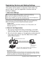
Page 37: ...ened Settings Items Settings are made for the Base Unit Name Unit of Temperature LAN Password and so on 2 Remote Unit Registration 1 After having completed the Base Unit Settings in the RTR 500W Setti...

Page 38: ...lp increase range and improve wireless communication It is also possible to register a Repeater to a Base Unit via a LAN connection 1 In the RTR 500W Settings Utility open the Repeater Unit Settings M...

Page 39: ...l Features and Functions 37 Changing Settings during Operation 37 Registering Remote Units via an RTR 500 37 LED Lamp Display 38 External Contact Output Input Terminals 39 What is the External Contact...

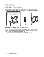
Page 40: ...pplied AC adaptor When using RTR 500W please connect the LAN cable to the HUB before supplying power LED Lamps before Starting Operation At this point if the Unit is properly running after having supp...

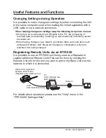
Page 41: ...e carried out When making changes via a network connection there are some items such as Network Settings LAN Password Changes or Initialization which are restricted from being changed Registering Remo...

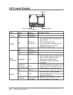
Page 42: ...Diagnosis ON In Diagnosis OFF Normal BLINKING Error Clock settings were not carried out or after a power outage the clock settings have been cleared The Remote Unit has not been registered DIAG and A...

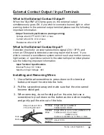
Page 43: ...nsor such as a motion sensor light sensor or open close sensor to the external input terminal please see the following important information Input Terminal Specifications Internal Pull up 3V 100k Maxi...

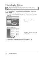
Page 44: ...are applications If it is necessary to uninstall the software please follow the steps below 1 In the Windows Start Menu click on Control Panel to open Windows XP Click the Add or Remove Programs Windo...

Page 45: ...stall Button Windows XP Click the Remove Button Windows Vista Windows 7 Click the Uninstall Button 4 The Install Shield Wizard window will appear Place a check next to Remove and click the Next button...

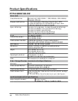
Page 46: ...MiniB Connector Optical Communication Wired LAN RTR 500NW Wireless LAN RTR 500AW LED Indicator POWER ACTIVE DIAG ALARM Dimensions H83mm x W102mm x D28mm excluding antenna Antenna Length 87 3mm Weight...

Page 47: ...of Current Readings FTP PASV mode also supported SMTP SMTP AUTH POP Before SMTP AUTH supports LOGIN only Warning Monitoring SMTP SMTP AUTH POP Before SMTP AUTH supports LOGIN only External Contact War...

Page 48: ...Compatible OS Microsoft Windows 7 32 64bit English Microsoft Windows Vista 32bit English Microsoft Windows XP 32bit SP2 or above English Operation under a 64bit OS is not guaranteed PC CPU A Stable Wi...

Page 49: ...Operation 45 Options Wall Attachment TR 5WK1 Materials PC Resin Screw for fastening to wall x 2 Double sided Tape x 1 Screw for fastening Unit x 1 Dimensions W106 x H86 x D17 8mm Screw holes 2 3 2mm U...

Page 50: ...Notes about Operation 46...

Page 51: ...Notes about Operation 47...

Reviews: