background image

1

About Data Collector RTR-57C

Outline

Our revolutionary Wireless RTR-5 series is a system wherein the various kinds 
of data measured and recorded by our data logger units (RTR-51/RTR-52-Tem-
perature data, RTR-53-Temperature and Humidity data, and RVR-52-Voltage, 
Pulse and Event data) can be transmitted to the RTR-57C Data Collector via 
short wave radio communication. The Data Collector can then be connected to 
your computer to enable easy downloading and total data management. The 
RTR-57C data collector can also be used to start recording and collect, check, 
and edit data on site for any of the units in the TR-5 Series (TR-51A/52) and/or 
the TR-7 Series (TR-71S/72S) making it unnecessary to collect the units and 
take them to your computer to carry out these functions.

Basic Functions

Wireless Data Communication Function

Our Thermo Recorder RTR-5 Series utilizes the RTR-57C to collect recorded 
temperature data from the RTR-51/RTR-52/ RTR-53 and RVR-52 units via our 
exclusive short-wave wireless technology. The RTR-57C also allows you to 
wirelessly control recording settings and start recording, as well as other functions 
of the data loggers. Communication is possible to a distance of up to 100 meters 
if unobstructed and direct.

Note:

 If collecting data via wireless communication, it is necessary to first set up 

the RTR-5 Series Units as Remote Units in your computer.

Register up to 3,840 RTR-5 Series Units on 1 RTR-57C

RTR-57C is designed to manage the RTR-5 Series Units in groups. 1 RTR-57C 
Unit can be set up to manage up to 60 groups, with each group containing up to 
64 RTR-5 Series Units. If being set up via computer each RTR-57C can be set to 
handle 15 groups with each group containing 250 RTR-5 Series Units.

Monitoring Function

With RTR-57C, you can wirelessly monitor current temperature readings of one 
group of RTR-5 Series Units, with the readings being sequentially displayed on 
the unit.

Note: 

If monitoring is carried out on a regular basis the battery life of the RTR-5 

Series Units will be shortened. For example, if the monitoring interval is set at 1 
minute the battery life will be about 4 months.

Easy Data Collection from a Variety of Unit Types

Data downloading can be carried out with any RTR-5 Series Units via wireless 
communication or by simply placing it face down on the communication pad area. 
Data from other types of units can be downloaded via the provided 
communication cable.

Data Capacity: 260,000 Readings

The RTR-57C has a large enough capacity to collect data from 16 RTR-51 units 
at full capacity. If not at full capacity, the RTR-57C can collect and manage data 
of up to 250 data downloading sessions. 

Graph Display

The RTR-57C gives you a high quality graph display of collected data whether it 
be temperature, humidity, voltage or pulse. Using the handy operation dial or the 
buttons on the front of the main unit you can easily scroll left and right across the 
graph display; giving you the data you want in an easy to check format.

Event List Display

The event data recorded on the RVR-52 can be downloaded and instantly displayed 
in an easy to read list. Using the handy operation dial or the buttons on the front of 
the main unit to scroll up and down the list you can easily check the event data.

Handy Operation Dial 

By simply moving the dial up and down you can scan the menu and make a selection 
by simply pressing in on the dial.

Monitor Temperature while Downloading

By making upper and lower limit settings on the RTR-57C you can monitor the 
recorded data as it is collected for irregularities and the results will be displayed. 
If any RTR-5 Series Unit has already been set with its own upper and /or lower 
limit, those values will take precedence over the values set in the RTR-57C.

Manage Recording Settings without a Computer

Besides controlling the collection of data, the RTR-57C can manage various 
recording settings such as: Recording Mode, Recording Interval, Programmed 
Recording Settings and Immediate Record. This enables the user to easily control 
various recording settings for a variety of models on-site without the need for a 
computer.

Summary of Contents for RTR-57C

Page 1: ...User s Manual Thank you for purchasing our product Carefully read this instruction manual before using this unit 2003 7 16004264060 Copyright 2001 2003 T D Corporation All rights reserved...

Page 2: ...d so please keep it in a safe place Please read the warranty and provisions for free repair carefully Notices about this User s Manual In order to properly use this product please carefully read this...

Page 3: ...s to the unit immediately turn the power OFF and remove the batteries Continued use may cause fire or electrocution Do not put your fingers or foreign matter into the communication port Do not use bat...

Page 4: ...mage and or insufficient contact In places which are not flat It may lead to the unit being dropped or falling and cause injury or damage In places exposed to fire or heat It may cause damage or a cha...

Page 5: ...tion Recording Start 29 Downloading Recorded Data 34 Graph Display 37 Event List Display 39 Other Functions Checking Upper and Lower Limits Setting the Upper and Lower Limit Range 41 Viewing the Resul...

Page 6: ...regular basis the battery life of the RTR 5 Series Units will be shortened For example if the monitoring interval is set at 1 minute the battery life will be about 4 months Easy Data Collection from...

Page 7: ...y Life varies according to type of battery measuring environment transmission frequency and ambient temperature This estimate of battery life was based on normal use under normal conditions using a ne...

Page 8: ...ation Dial Moving the dial up and down By moving the dial up or down the arrow will move to allow you to choose the desired item The selected part will be displayed in an easy to see inversed shade Wh...

Page 9: ...adjust the arrow to BACK and press it to complete the setting and take you back to the menu display When carrying out a Remote Unit search a mark will appear next to Group Names in which Remote Units...

Page 10: ...d of batteries Install the batteries in the correct direction to align and Battery charging via the main unit is impossible If you use an outside power source batteries are not necessary The RTR 57C u...

Page 11: ...and the recorded time of downloaded data will be different from the actual one so please set the date and time accurately When changing the battery the time of the main unit may become incorrect pleas...

Page 12: ...rder for Windows 100 meters Remote Unit Remote Unit Group 14 Read Logger Settings The RTR 57C can read and display all settings for any selected data logger that has been registered Search for Remote...

Page 13: ...a to your computer connect the RTR 57C Unit to your computer with the communication cable provided NOTE Wireless communication cannot be done with the computer Communicating with the Computer 15 Commu...

Page 14: ...ration NOTE Wireless communication can only be carried out with RTR 51 52 53 and RVR 52 units that have been registered as Remote Units via the provided software T D Recorder for Windows Please extend...

Page 15: ...ion before making any changes See p 24 for details Wireless Communication Recording Start Wireless Communication Recording Start Select a Group in which Remote Units are registered Select a Remote Uni...

Page 16: ...usly overwritten Recording Interval Choose from 15 intervals 1 2 5 10 15 20 30 seconds and 1 2 5 10 15 20 30 and 60 minutes 3 Make Recording Condition Settings Before selecting a Remote Unit you can r...

Page 17: ...ction For details about how to lift the protection see the Help Menu in the provided software T D Recorder for Windows or see its User s Manual About Reading the Recording Settings Select a Remote Uni...

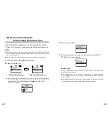
Page 18: ...unication is possible will appear with a mark next to them See p 45 for details 25 Wireless Communication Downloading Recorded Data Select a Group in which Remote Units are registered Select the Remot...

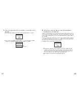
Page 19: ...ved in the RTR 57C and the data cannot be saved the message Memory Full will be displayed and the downloading will be canceled Carry out any new download only after having downloaded and saved the rec...

Page 20: ...gs mean The recording conditions of a specified Remote Unit can be read into an RTR 57C unit If you wish to restart recording without making any changes to the recording conditions specify the Remote...

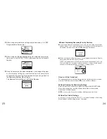
Page 21: ...o the menu The Remote Unit will start recording 32 3 Move the arrow to Programmed after setting the conditions 4 Set the recording start time and move the arrow to REC START 1 In the Main Menu open RE...

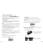
Page 22: ...r Please make sure to place the unit within the ridges for an exact fit Place logger face down on RTR 57C For TR 71S 72S Connect using the included communication cable TR 3C10 34 Download recorded dat...

Page 23: ...d Result If the amount of main unit memory is low the downloading of recorded data may be impossible When you check the amount of the memory to confirm whether the data you wish to download can be sav...

Page 24: ...e displayed when Set Limits has been set as ON Graph Display OK CH1 38 Cursor Bar Fixed Display Cursor position is displayed and measurement information is displayed at the top of the LCD display Uppe...

Page 25: ...the data at the cursor position Arrows Rising Edge Data Falling Edge Data Both Rising and Falling within 1 second 40 Measurements are taken every second and events are recorded if any changes have oc...

Page 26: ...s to the value click to activate the new setting Upper Limit Lower Limit By holding down the buttons on the main unit you can make rapid changes to the values Pressing the button will make the value l...

Page 27: ...ppear with a mark next to them See p 45 for details 1 In the Main Menu open Gather Data 2 Select the Remote Unit you wish to view 3 Click Get Rmote Info 4 Once communication has been completed the Rem...

Page 28: ...ames with which communication is possible This function can be useful when selecting Remote Units for downloading data or starting recording 1 In the Main Menu open SEARCH RMOTE 2 Select the search ra...

Page 29: ...ring Interval Interval The monitoring interval is the amount of time between the starting of wireless communication to gather current Remote Unit readings Selections can be made from 15 sec 30 sec and...

Page 30: ...ar 50 Viewing a data list Unregistered data loggers will appear by channel name If a channel name shows This means that when the recording conditions were set via direct cable connection between the d...

Page 31: ...deletion process 52 Deleting All Data Recording Conditions and other settings will not be deleted Recording conditions can be returned to the original factory settings by going to REC SETTINGS Initia...

Page 32: ...and down to make it lighter 1 In the Main Menu open SET FUNCTIONS and Backlight 3 Move the arrow to and click BACK to finish 54 Muting the Operations Buzzer Checking Memory Number of Saved Readings T...

Page 33: ...or change Temperature Unit display settings for each data logger in the Recording Start Settings display in the supplied software For details see the Help menu in T D Recorder for Windows or the User...

Page 34: ...BACK BACK Display Graph See p 37 Judge See p 41 Select Delete See p 51 Displays the graph for that data View results of judgement After confirmation select OK to finish MONITOR MODE View Current Meas...

Page 35: ...yed if you have selected Wireless and Package Record Standby Call by Group 60 BACK Upper and Lower Limit Settings See p 41 Backlight See p 53 Set Clock See p 11 Check Memory See p 54 Clear Memory See...

Page 36: ...ess Method ETSI EN300 220 Transmission Distance Up to 100 meters May vary with conditions Interface Communication Speed Special Short Wave Radio Type approx 2 000bps min with data logger Modular Jack...

Page 37: ...estimated here is calculated using a new battery under normal operating conditions and is no way should be understood as a guarantee of battery life 2 Operating temperature depends on the specificatio...

Page 38: ...5 Sensor Temperature Durability 70 to 180 Water Resistance Splash Proof Sensor and Cable Measurement Accuracy Average 0 3 20 to 80 Average 0 5 40 to 20 80 to 110 Average 1 0 60 to 40 110 to 155 66 Sen...

Page 39: ...r Resistance 100 Output 2V at 20mA 0 4V at 4mA Conversion Accuracy 0 5 Cable Length 1 5 m Materials M3 5 Crimp Terminal Vinyl Coated Electrical Wire Input Cables Optional 68 Wall Attachment TR 05K2 Ma...

Page 40: ...about our company news products upcoming events software and user s guides downloads as well as other support Please stop by and see what we have to offer http www tandd jp This is printed on 100 recy...

Reviews: