background image

All rights of this User’s Manual belong to T&D Corporation. It is prohibited to 

use, duplicate and

/

or arrange a part or whole of this User’s Manual without 

the permission of T&D Corporation.

Microsoft  and Windows  are registered trademarks of Microsoft Corporation 

USA and are binding in the USA and all other countries. Company names 
and  product  names  are  trademarks  or  registered  trademarks  of  each 
company.

Specifications, design and other contents outlined in this manual are subject 

to change without notice.

On  screen  messages  in  this  manual  may  vary  slightly  from  the  actual 
messages.

Please notify the shop where you purchased this product or T&D Corporation 

of any mistakes, errors or unclear explanations in this manual. T&D Corporation 
accepts no responsibility for any damage or loss of income caused by the use 
of our product.

This product has been designed for private or industrial use only. It is not for 

use in situations where strict safety precautions are necessary such as in 
connection with medical equipment, whether directly or indirectly.

We are not responsible for any malfunction or trouble caused by the use of 
our product or by any problem caused by the use of measurement results 
of our unit. Please be fully aware of this before using our product.

Some of our products, which come under the category of strategic goods in 
foreign trade law, need the permission of the Japanese government to be 
exported outside of Japan. 

This User’s Manual cannot be reissued, so please keep it in a safe place.

Please read the warranty and provisions for free repair carefully.

Notices about this User’s Manual

In order to properly use this product, please carefully read this manual before 

using.T&D Corporation accepts no responsibility for any malfunction of and

/

or 

trouble with this product or with your computer that is caused by the improper 

handling of this product and will deem such trouble or malfunction as falling 

outside the conditions for free repair outlined in the attached warranty.

To  ensure  safety  be  sure  to  obey  all  of  the  following 

warnings.

The following items should be strictly obeyed for the safe usage of this unit, 
and for protecting yourself and other people from bodily harm and

/

or damage 

to property. To ensure the proper use of our product, please read the following 
carefully and fully understand the contents.

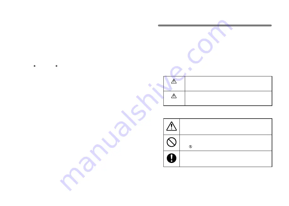
Explanation of Symbols

Safety Precautions and Instructions 

Explanation of Warning Symbols

DANGER

These  entries  are  actions  that  absolutely  under  no 
circumstance  should  be  taken. The  taking  of  such  an  action 
may cause serious personal physical damage or death.

CAUTION

These  entries  are  actions  that  if  taken  may  lead  to  physical 
injury or damage to persons or things.

Explanation of Picture Symbols

Denotes an important warning or caution. 

Denotes a forbidden action. Inside or near the symbol will appear 
another symbol giving details. 

(

EX:  

stands for DO NOT TAKE APART

)

Denotes an action that you must take. 

Summary of Contents for TR-71U

Page 1: ...User s Manual Thank you for purchasing our product Carefully read this instruction manual before using this unit 2004 01 16004374020...

Page 2: ...rmission of the Japanese government to be exported outside of Japan This User s Manual cannot be reissued so please keep it in a safe place Please read the warranty and provisions for free repair care...

Page 3: ...top using Continued use may cause fire or electrocution Condensation may occur if the unit is moved from one environment to another where the difference in temperature is great Use the unit in an envi...

Page 4: ...r batteries than those that are specified in this User s Manual It may cause a fire or other trouble including malfunction CAUTIONS The possible temperature measurement range for this sensor is 40 to...

Page 5: ...ickers shows abnormality you should change the old sensor to a new one immediately Cautions about using the Sensors Wetness Detection Sticker Temperature Detection Sticker Wetness Detection Sticker In...

Page 6: ...d Specifications and explanations used in this User s Manual are based on operations carried out with a new battery and are in no way a guarantee of your actual battery life Battery Life Warning Displ...

Page 7: ...t Software User s Manual 1 AA Alkaline Battery LR6 1 USB Communication Cable US 15C 1 T D Recorder for Windows Software CD ROM 1 TR 72U USB Communication Cable US 15C 1 AA Alkaline Battery LR6 1 Tempe...

Page 8: ...2000 readings the scale will be marked from left to right COM Mark This will appear when data is being sent or received ON USB cable is connected BLINKING In communication with computer Recording Mod...

Page 9: ...o download all saved recorded data 3 If the battery is further left unchanged the display will automatically shut off If all battery power is lost all data will be lost as well NOTE If a unit is left...

Page 10: ...Driver 3 Insert the attached CD ROM in the CD ROM drive If the Installation Window opens close it For Windows XP 1 Turn on your computer and open Windows 2 After Windows has been completely started u...

Page 11: ...ger 12 3 Insert the attached CD ROM in the CR ROM drive If the Installation Window opens close it 4 By connecting a data logger to the USB cable already connected to your computer the Found New Hardwa...

Page 12: ...Next button 14 8 By clicking the Next button installation will begin 9 After completing installation click the Finish button If the Driver is not automatically detected please search by specifying th...

Page 13: ...SB Recorder COM For Windows Me 1 Turn on your computer and open Windows 2 After Windows has been completely started up connect the supplied USB cable to a USB port on your computer 3 Insert the attach...

Page 14: ...M Device Driver and install manually from there Checking After Connecting 1 Open the Control Panel and double click on System the system properties will be displayed 2 Click the Device Manager Tab and...

Page 15: ...ere you can choose how you wish to find the driver file For Windows 98 1 Turn on your computer and open Windows 2 After Windows has been completely started up connect the supplied USB cable to a USB p...

Page 16: ...place as CD ROM Device Driver and install manually from there Checking After Connecting 1 Open the Control Panel and double click on System the system properties will be displayed 2 Click the Device M...

Page 17: ...t on the surface of the sensor causing the sensor s accuracy and sensitivity to decrease If the sensor is being used in a bad environment smoky or dusty places it may be necessary to change the sensor...

Page 18: ...ng interval will be displayed 15 seconds 15 minutes By pressing the REC switch on the main unit you can start a recording session immediately If you wish to make changes to the device name channel nam...

Page 19: ...hermistor Macromolecular Humidity Sensor Recording Interval Select from 15 choices 1 2 5 10 15 20 30 seconds 1 2 5 10 15 20 30 60 minutes Recording Capacity 8000 readings 2 channels Recording Modes En...

Page 20: ...nstant Time In the air Approx 75 Sec TR 0206 Stainless Protection Sensor Cable Length 0 6m Thermal Constant Time In the air Approx 75 Sec Materials Thermistor TPE resin shielded sensor TPE resin shiel...

Page 21: ...ble Temp Sensor Only TR 1C30 Cable length 3 0m Materials Vinyl Coated Electrical Wire unit millimeters Materials Temperture humidity sensor Polypropylene resin Vinyl Coated Electrical Wire Possible te...

Page 22: ...to the dealer A service charge may be added if a repairperson must be sent out to the place of use for repair 3 If you have moved after purchasing or the product was received as a gift or there are d...

Reviews: