TABLE 1-2
POWER REQUIREMENTS
1 .
+ 5 V o l t s :
2. + 2 4 V o l ts: After motor start interval
0.70 Amps typical
Spindle Moto r
0 .3 5 A m p s t y p ical
Stepper Moto r
0.4 0 A m p s t y p ical
Electronics
0.17 Amps typical
Total
0.92 Amps typical
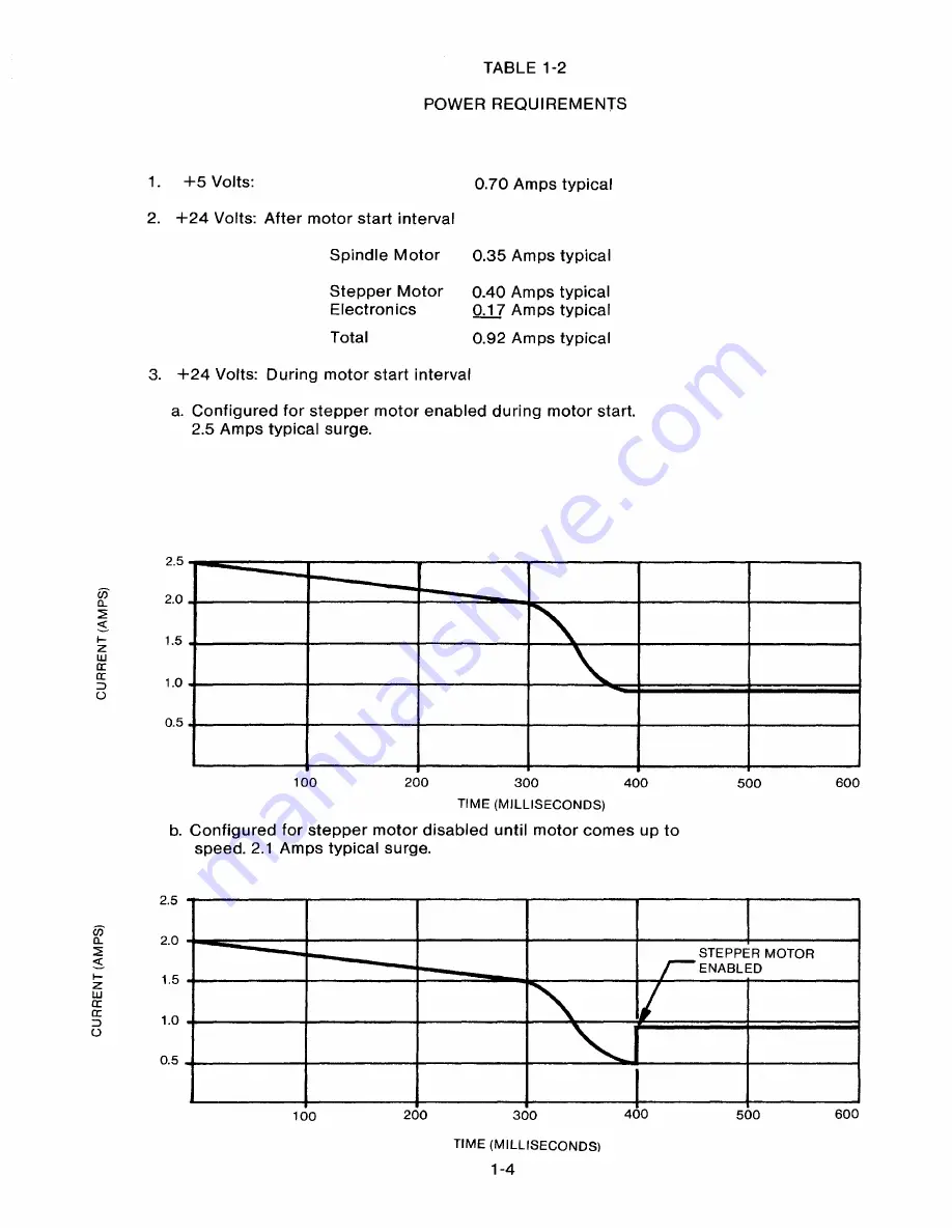
3. + 2 4 V o l ts: D u ring motor start interval
a. Configured for stepper motor enabled during motor start.
2.5 Amps typical surge.
2.5
2.0
1.5
1.0
0.5
100
200
300
400
600
500
TIME (MILLISECONDS)
b. Configured for stepper motor disabled until motor comes up to
speed. 2.1 Amps typical surge.
2.5
2.0
STEPPER MOTOR
ENABLED
1.5
1.0
0.5
200
300
400
500
600
100
TIME (MILLISECONDSI
1-4
Summary of Contents for TM848-1
Page 32: ...HUB CENTER LINE TRACK 0 TRACK 38 TRACK 76 Figure 2 2 Hub Center Line and Track Locations 2 3 ...
Page 81: ...APPENDIX I PRINTED CIRCUIT BOARD S CHEM A T ICS AND ASSEM B LY DRAW IN G S ...
Page 88: ...APPENDIX II RECOM M E N D E D SPARE PARTS LIST ...
Page 90: ...Pi N 1 79031 001 1 082 ...


