1.19.1
Dri v e S e l ect DS1-DS4
This option allows the user to daisy chain up to four drives, and to enable one drive at at time.
Drive select is implemented by shorting one of the four connections, using a shorting plug. The drive
comes equipped from the factory with DS1 installed. All outputs are gated with drive select, as set-up
at the factory.
1 .19.2
S id e S e l ect O pt ions Using Drive Select 1B - 4 B
This option allows the user to select the head to be used with drive select.
Side Select options are implemented by removing the shorting plug from the DS1-DS4 option pads,
installing Pins 1 B-4B, and connecting the shorting plug to the desired 1 B-4B pins. S2 should be etch
cut, and S3 installed (see Section 1.18).
1.19.3
I n U s e F r o m Drive Select (Z)
This option allows the user to enable the activity L. E. D. when the drive is selected.
In Use From Drive Select is factory installed.
1.19.4
In Us e F r o m H e ad Load (Y)
This option allows the user to use the head load line to enable the Activity L. E. D.
In Use From Head Load is implemented by punching out Option Z between Pins 1 and 16 of U3. A
jumper must be installed at location Y.
1.19.5
Read y A l t e r nate Output Pad (R)
This low going signal is derived by gating the internal ready and drive select to give the controller a
true (low) ready status of the drive.
. The Ready Alternate Output Pad is factory installed.
1.19.6
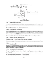
R a d i al Ready (RR)
This option allows the user to monitor the ready status of all drives without selecting them. This option
cannot be used concurrently with individual motor control lines for each drive. (see Figure 1-8).
Radial Ready is implemented by punching out Option R between Pins 7 and 10 of U3, by etch cutting
RR, then by running a wire from U4, Pin 3 to the desired alternate output lines 4, 6, 8, and 24.
1-18
Summary of Contents for TM848-1
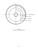
Page 32: ...HUB CENTER LINE TRACK 0 TRACK 38 TRACK 76 Figure 2 2 Hub Center Line and Track Locations 2 3 ...
Page 81: ...APPENDIX I PRINTED CIRCUIT BOARD S CHEM A T ICS AND ASSEM B LY DRAW IN G S ...
Page 88: ...APPENDIX II RECOM M E N D E D SPARE PARTS LIST ...
Page 90: ...Pi N 1 79031 001 1 082 ...


