DREDv +
PROGRAM SHUNT PINS 7-10 ARE OPENED
R14
4 7 R 4
I
05
44
4 ..
4
IIEA AY ~E
I
SIDE 1-
IN1 FF+
IREADY-
DRSEL -I
L'502,
Oa
4
LAOK
I
Ua
I/i'
tl
II
%5V
R99
150
RR
M 2~
ETCH CUT
RA7ilK
~READ
STATUS
TO USER
CONTROLLER
i XM cc
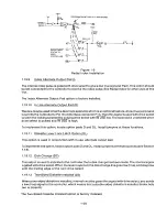
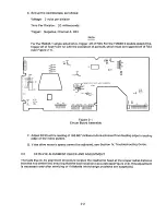
Figure 1-8
Radial Ready Installation
Note
MC1 through MC4 cannot be used as radial motor control when using this option.
1.19.7
Rea d y , M o d ified (RM)
This option allows the drive to write on the upper surface of a single-sided diskette. It prevents the
drive from making Ready become false when the upper surface of a single-sided diskete is selected.
To implement this option, connect a jumper at the RM pads.
1.19.8
Ra di a l I n dex (Rl)
This option uses the alternate I/O lines for radial index lines. This option allows the user to monitor the
index of each drive independent of drive select. This option cannot be used concurrently with radial
ready, or with independent motor control.
Radial Index is implemented by removing the shunt bridge at U3, Pins 6 and 11, by etch cutting radial
index, and by running a wire from U4, Pin 6, to the appropriate alternate I/O lines. If use of MC1 is
desired, interface line 20 ma y b e u sed as on e i n dex line. In this case, the shunt pack, U3, 6-11,
remains intact on one d rive, (see Figure 1-9).
1-19
Summary of Contents for TM848-1
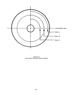
Page 32: ...HUB CENTER LINE TRACK 0 TRACK 38 TRACK 76 Figure 2 2 Hub Center Line and Track Locations 2 3 ...
Page 81: ...APPENDIX I PRINTED CIRCUIT BOARD S CHEM A T ICS AND ASSEM B LY DRAW IN G S ...
Page 88: ...APPENDIX II RECOM M E N D E D SPARE PARTS LIST ...
Page 90: ...Pi N 1 79031 001 1 082 ...

