S ECTION I I
M AINTENA NCE C H E CKS AND ADJUST M E N T S
2.
INTR O DUGTI ON
This section is for the use of the OEM Repair Department. It contains checks and adjustments that are
used during the normal life of the drive.
Before applying power to the drive or doing any checks or adjustments, visually inspect the drive to
ensure that it has no missing or broken parts.
The following equipment is required for checks and adjustments:
1. A dual-channel, wideband oscilloscope:
T e k t r o nix 465 or equivalent
2. An exerciser or software routine capable of stepping the drive to any track, selecting the
upper or lower head, and writing a 1F, all zeros if FM,or a 2F, all ones if FM, pattern on the disk.
3. A Phillips screwdriver
4. A set of Allen wrenches
5. A flat blade screwdriver
6. A blank diskette
7. An alignment diskette :
D y s a n P/ N 3 6 0 / 2 A or eq uivalent
8 . Integrated circuit dip clips, 14 and 16 p i n
S PINDLE DRIVE MO TO R C H E C K S AN D AD J U S T M E N T S
2.1
The long-term drive motor speed adjustment ensures that the motor's speed is within the range of
tolerance specified. The motor speed specification is 360 RPM + 1 .25 pe rcent.
2.1.1.
Lo ng - T e r m Drive Motor Speed Checks and Adjustments
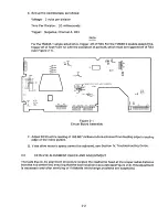
A. Preliminary checks required:
Verify power: + 2 4 V D. C. +10 pe rcent
+ 5V D. C. ~ 5 p e r c e n t
B. Apply power to the drive.
C. Activate the drive motor on the interface line.
D. Insert a work diskette.
2-1
Summary of Contents for TM848-1
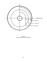
Page 32: ...HUB CENTER LINE TRACK 0 TRACK 38 TRACK 76 Figure 2 2 Hub Center Line and Track Locations 2 3 ...
Page 81: ...APPENDIX I PRINTED CIRCUIT BOARD S CHEM A T ICS AND ASSEM B LY DRAW IN G S ...
Page 88: ...APPENDIX II RECOM M E N D E D SPARE PARTS LIST ...
Page 90: ...Pi N 1 79031 001 1 082 ...


