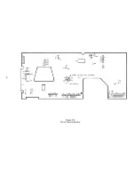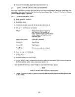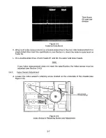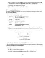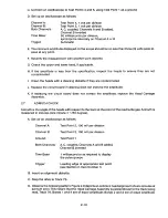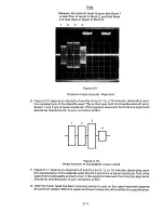
E. Set up the oscilloscope, as follows:
Voltage: 2 volts per division
Time Per Division: 20 milliseconds
Trigger:
N e g a t i ve, Channel A, R33
Note
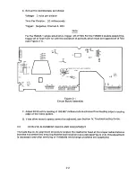
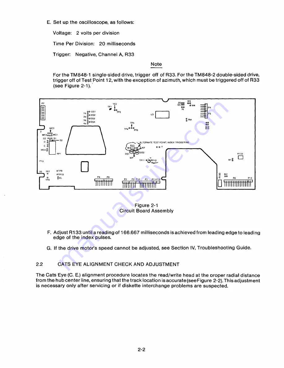
For the TM848-1 single-sided drive, trigger off of R33. For the TM848-2 double-sided drive,
trigger off of Test Point 12, with the exception of azimuth, which must be triggered off of R33
(see Figure 2-1).
M3
DCOO
0 M4
2SOO
00
Rl
00 DS I
ob DS2
Ib 0
2b 0 OODS3
3b 0
OODS4
0
0 RM
4b 0
f
TP40 0 0
TP5
MC3
00
00
14 Cb
IX O
PTS
MC200
3
MCI
0
S 2 00 0 5 1
0 0
S2
C 0
MC4 o
R33
O O Y
ALTERNATE TEST POINT, INDEX TRIGGERING
NP
00 DS2
Ds1
WP
M I
II
TPII O
Q
O P 1 2
50
TP T
OTPS
8
M2
0
TPS
OTPIO
0 DL
IZ
00
PS
P14
P2
P 3 PI O
P I
PI I P 12
Figure 2-1
Circuit Board Assembly
F. Adjust R133 until a reading of 166.667 milliseconds is achieved from leading edge to leading
edge of the index pulses.
G. If the drive motor's speed cannot be adjusted, see Section IV, Troubleshooting Guide.
2 .2
C A T S E Y E ALIG N M E N T C H E C K AN D AD J U S T M E N T
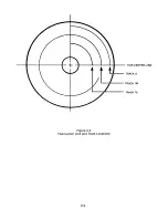
The Cats Eye (C. E.) alignment procedure locates the read/write head at the oroper radial distance
from the hub center line, ensuring that the track location is accurate(seeFigure 2-2). This adjustment
is necessary only after servicing or if diskette interchange problems are suspected.
2-2
Summary of Contents for TM848-1
Page 32: ...HUB CENTER LINE TRACK 0 TRACK 38 TRACK 76 Figure 2 2 Hub Center Line and Track Locations 2 3 ...
Page 81: ...APPENDIX I PRINTED CIRCUIT BOARD S CHEM A T ICS AND ASSEM B LY DRAW IN G S ...
Page 88: ...APPENDIX II RECOM M E N D E D SPARE PARTS LIST ...
Page 90: ...Pi N 1 79031 001 1 082 ...


