2.2.1
Cat s Eye Alignment Check
A. Set up an oscilloscope, as follows:
Channel A;
Channel B:
Test Point 2 alternate is Test Point 4 on R30
Test Point 3 alternate is Test Point 5 on R29
Test Point 1
Ground
Read Differentially:
A plus B, B inverted
Time Base:
External Trigger:
20 milliseconds per division
Test Point 11, negative trigger, for single-sided drives. Test Point
12„negative trigger, for double-sided drives. R33 (end closest to
DS2), negative trigger, is an alternate test point for both single- and
double-sided drives.
B. Apply power to the drive.
Note
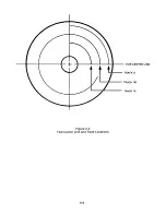
The Track 38 radius is 2.8207 2.0020. Other track locations are computed based upon 48TPI.
C. Select the drive at the interface.
D. Insert the alignment diskette into the drive.
E. Select Head 00, the lower head.
F. Seek to and observe Track 38 for Cats Eye alignment of the lower head.
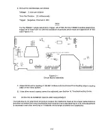
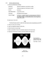
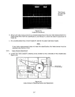
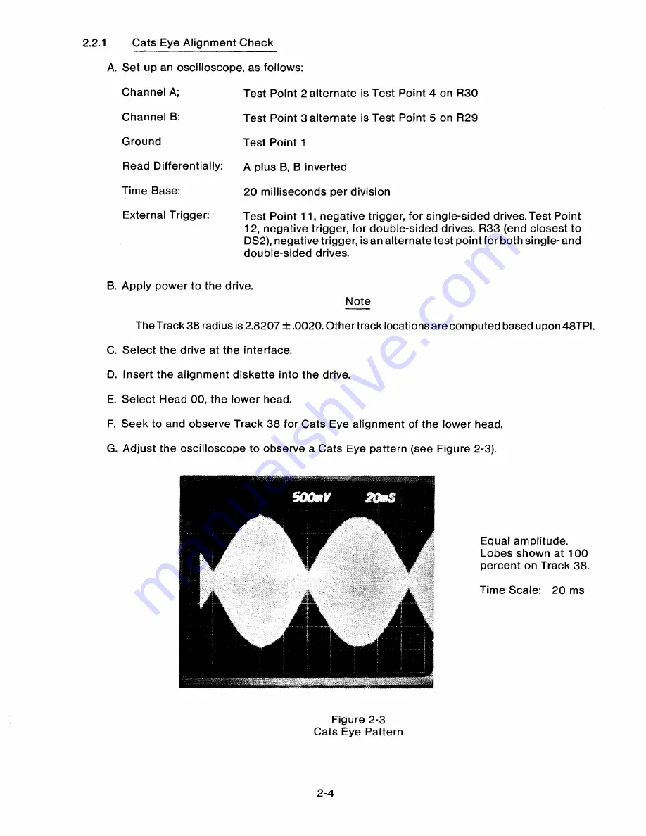
G. Adjust the oscilloscope to observe a Cats Eye pattern (see Figure 2-3).
Equal amplitude.
Lobes shown at 100
percent on Track 38.
Time Scale: 20 ms
Figure 2-3
Cats Eye Pattern
2-4
Summary of Contents for TM848-1
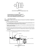
Page 32: ...HUB CENTER LINE TRACK 0 TRACK 38 TRACK 76 Figure 2 2 Hub Center Line and Track Locations 2 3 ...
Page 81: ...APPENDIX I PRINTED CIRCUIT BOARD S CHEM A T ICS AND ASSEM B LY DRAW IN G S ...
Page 88: ...APPENDIX II RECOM M E N D E D SPARE PARTS LIST ...
Page 90: ...Pi N 1 79031 001 1 082 ...


