3
4
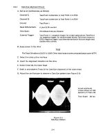
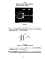
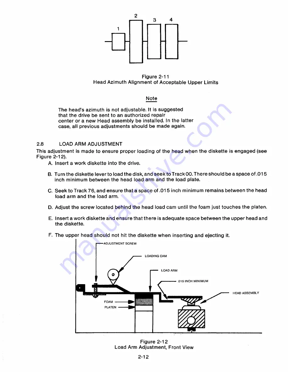
Figure 2-11
Head Azimuth Alignment of Acceptable Upper Limits
Note
The head's azimuth is not adjustable. It is suggested
that the drive be sent to an authorized repair
center or a new Head assembly be installed. In the latter
case, all previous adjustments should be made again.
2.8
LOA D A R M A D J U S T MENT
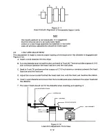
This adjustment is made to ensure proper loading of the head when the diskette is engaged (see
Figure 2-12).
A. Insert a work diskette into the drive.
B. Turn the diskette lever to load the disk, and seek to Track 00. There should be a space of.015
inch minimum between the head load arm and the load plate.
C. Seek to Track 76, and ensure that a space of.015 inch minimum remains between the head
load arm and the load arm.
D. Adjust the screw located behind the head load cam until the foam just touches the platen.
E. Insert a work diskette and ensure that there is adequate space between the upper head and
the diskette.
F. The upper head should not hit the diskette when inserting and ejecting it.
ADJUSTMENT SCREW
LOADING CAM
LOAD ARM
.015 INCH MINIMUM
HEAD ASSEMBLY
FOAM
PLATEN
Figure 2-12
Load Arm Adjustment, Front View
2-1 2
Summary of Contents for TM848-1
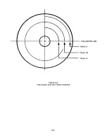
Page 32: ...HUB CENTER LINE TRACK 0 TRACK 38 TRACK 76 Figure 2 2 Hub Center Line and Track Locations 2 3 ...
Page 81: ...APPENDIX I PRINTED CIRCUIT BOARD S CHEM A T ICS AND ASSEM B LY DRAW IN G S ...
Page 88: ...APPENDIX II RECOM M E N D E D SPARE PARTS LIST ...
Page 90: ...Pi N 1 79031 001 1 082 ...

