DRIVE BELT
SMALL
FLANGED
SPINDLE
PULLEY
0
0 0
Oe
LARGE
SPINDLE
PULLEY
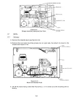
Figure 5-1
Drive Belt and Spindle
B. Grasp the drive belt, and remove it from the pulleys.
5 .1.2
I nst a l l a t i o n
A. With the shiny side inward, loop the new drive belt onto the small, flanged spindle pulley.
B. While turning the spindle, put the drive belt on the large spindle pulley.
5.1.3
C hec k s
A. After turning the drive motor on, check that the drive belt does not slip or fall off the large
pulley.
B. Check the spindle speed (see Section II).
5 .2
DRIV E M O T O R
Removal
5.2.1
A. Remove the drive belt (see Section 5.1).
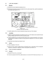
B. After turning the drive over, cut the tie wraps that hold the drive motor's wires(see Figure 5-2).
C. Unplug P6 from the circuit board.
D. Remove the three mounting screws that attached the drive motor to the chassis.
E. Lift out the drive motor.
5 .2.2
Ins t a l l a t i o n
A. Set the drive motor on the chassis, aligning the three mounting holes.
B. Reinstall and tighten the three mounting screws.
5-2
Summary of Contents for TM848-1
Page 32: ...HUB CENTER LINE TRACK 0 TRACK 38 TRACK 76 Figure 2 2 Hub Center Line and Track Locations 2 3 ...
Page 81: ...APPENDIX I PRINTED CIRCUIT BOARD S CHEM A T ICS AND ASSEM B LY DRAW IN G S ...
Page 88: ...APPENDIX II RECOM M E N D E D SPARE PARTS LIST ...
Page 90: ...Pi N 1 79031 001 1 082 ...

