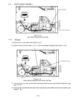
MOUNTING SCREWS (2 EA SIDE)
BRIDGE ASSY
Q4
INDEX L.E.D.'s (2)
4 O
4
p
p
~D
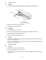
I S K ETTE LEVER
4
p
Q4
0o
SHAFT
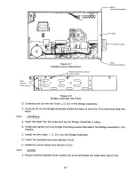
Figure 5-9
MO U NTING SCREWS
(2 EA SIDE)
Bridge Assembly Additional Key Parts
BEZEL
5.7
5.7.1
R emov a l
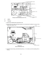
A. Remove the diskette lever (see Section 5.5).
B . Remove the f our b e zel mo u nting screws, two on e ac h s i de, that attach the b e zel to t h e
chassis (see Figure 5-10).
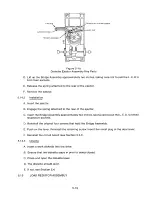
BEZEL
MO U NTING SCREWS 2
BEZEL
0+ .. 0+
P 2 P3
P I
~
DISK E T TE LEVER
Oo
BEZEL
MO U NTING SCREWS. 2
Figure 5-10
Bezel and Related Parts
C. Lift off the bezel, being careful that the Activity L. E. D. comes out of its mounting with no
binding.
5-8
Summary of Contents for TM848-1
Page 32: ...HUB CENTER LINE TRACK 0 TRACK 38 TRACK 76 Figure 2 2 Hub Center Line and Track Locations 2 3 ...
Page 81: ...APPENDIX I PRINTED CIRCUIT BOARD S CHEM A T ICS AND ASSEM B LY DRAW IN G S ...
Page 88: ...APPENDIX II RECOM M E N D E D SPARE PARTS LIST ...
Page 90: ...Pi N 1 79031 001 1 082 ...

