5 .7.2
Ins ta l l a t i o n
A. Put the bezel on the drive, ensuring that the Activity L. E. D. goes into its holder.
B. Install the four bezel mounting screws that attach the bezel to the chassis.
5.7.3
C hec ks
A. Ensure that the Activity L. E. D. goes on when required.
B. Ensure that the diskette lever clamps the cone and loads the head.
ACTIVITY L. E. D.
5.8
Removal
5.8.1
A. Remove the bezel (see Section 5.7.1).
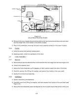
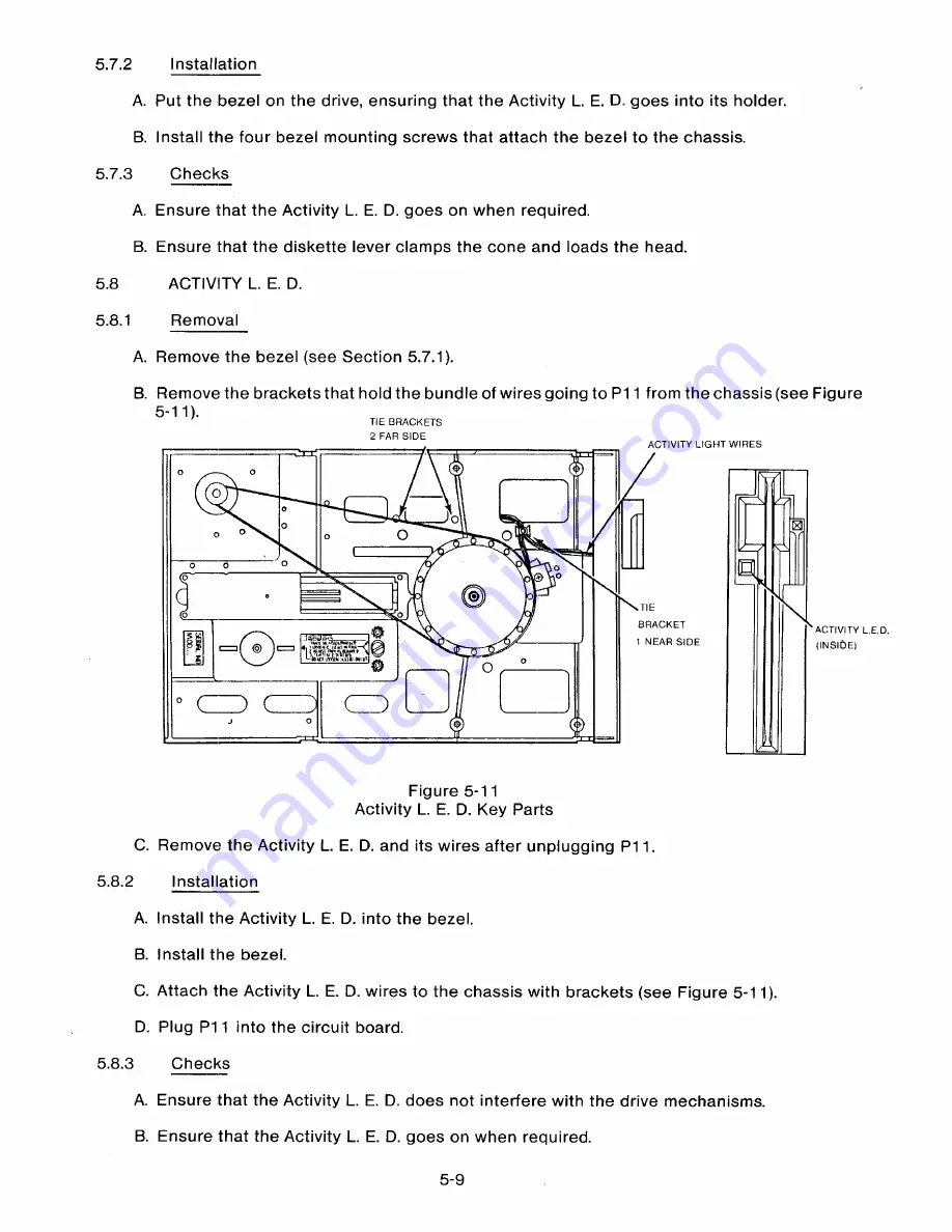
B. Remove the brackets that hold the bundle of wires going to P11 from the chassis (see Figure
5-1 1).
TIE BRACKETS
2 FAR SIDE
ACTIVITY LIGHT WIRES
C
o
o
0
Qo
TIE
BRACKET
1 NEAR SIDE
ACTIVITY L.E D
(INSIDE)
Figure 5-11
Activity L. E. D. Key Parts
C. Remove the Activity L. E. D. and its wires after unplugging P11.
5.8.2
Installation
A. Install the Activity L. E. D. into the bezel.
B. Install the bezel.
C. Attach the Activity L. E. D. wires to the chassis with brackets (see Figure 5-11).
D. Plug P11 into the circuit board.
5.8.3
C hec k s
A. Ensure that the Activity L. E. D. does not interfere with the drive mechanisms.
B. Ensure that the Activity L. E. D. goes on when required.
5-9
Summary of Contents for TM848-1
Page 32: ...HUB CENTER LINE TRACK 0 TRACK 38 TRACK 76 Figure 2 2 Hub Center Line and Track Locations 2 3 ...
Page 81: ...APPENDIX I PRINTED CIRCUIT BOARD S CHEM A T ICS AND ASSEM B LY DRAW IN G S ...
Page 88: ...APPENDIX II RECOM M E N D E D SPARE PARTS LIST ...
Page 90: ...Pi N 1 79031 001 1 082 ...

