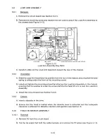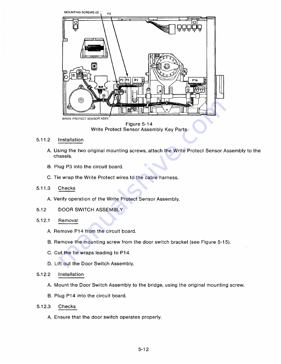
MOUNTING SCREWS (2) '
$ . . $
P2 P3
P I
Oo
0o
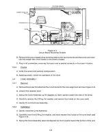
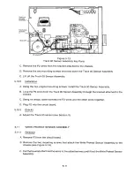
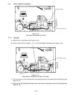
WRITE PROTECT SENSOR ASSY.
Figure 5-14
Write Protect Sensor Assembly Key Parts
5.11.2
Ins t a l l a t ion
A. Using the two original mounting screws, attach the Write Protect Sensor Assembly to the
chassis.
B. Plug P3 into the circuit board.
C. Tie wrap the Write Protect wires to the cable harness.
5.11.3
C hec k s
A. Verify operation of the Write Protect Sensor Assembly.
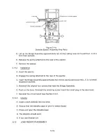
D OO R SW ITCH ASS E M B L Y
5.1 2
5 .12.1
Re m o v a l
A. Remove P14 from the circuit board.
B. Remove the mounting screw from the door switch bracket (see Figure 5-15).
C. Cut the tie wraps leading to P14.
D. Lift out the Door Switch Assembly.
5.12.2
I ns t a l l a t io n
A. Mount the Door Switch Assembly to the bridge, using the original mounting screw.
B. Plug P14 into the circuit board.
5 .12.3
Chec k s
A. Ensure that the door switch operates properly.
5-1 2
Summary of Contents for TM848-1
Page 32: ...HUB CENTER LINE TRACK 0 TRACK 38 TRACK 76 Figure 2 2 Hub Center Line and Track Locations 2 3 ...
Page 81: ...APPENDIX I PRINTED CIRCUIT BOARD S CHEM A T ICS AND ASSEM B LY DRAW IN G S ...
Page 88: ...APPENDIX II RECOM M E N D E D SPARE PARTS LIST ...
Page 90: ...Pi N 1 79031 001 1 082 ...

