5 .16
STE PP E R B A N D
5 .16.1
Re mo v a l
It is suggested that the drive be returned to an authorized Tandon repair center when removing the
stepper band.
A. Remove the circuit board (see Section 5.3.1).
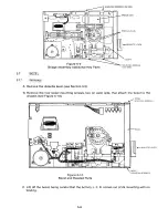
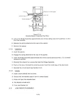
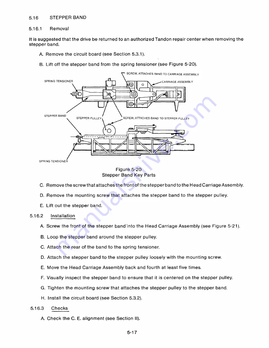
B. Lift off the stepper band from the spring tensioner (see Figure 5-20).
S CREW, ATTACHES BAND TO CARRIAGE ASSEMB LY
SPRING TENSIONER
~C A R RIAGE ASSEMBLY
0
O
Qo
STEPPER BAND
STEPPER PULLEY
SCREW, ATTACHES BAND TO STEPPER PULLEY
SPRING TENSIONER
Figure 5-20
Stepper Band Key Parts
C. Remove the screw that attaches the front of the stepper band to the Head Carriage Assembly.
D. Remove the mounting screw that attaches the stepper band to the stepper pulley.
E. Lift out the stepper band.
5.16.2
Ins t a l l a t io n
A. Screw the front of the stepper band'into the Head Carriage Assembly (see Figure 5-21).
B. Loop the stepper band around the stepper pulley.
C. Attach the rear of the band to the spring tensioner.
D. Attach the stepper band to the stepper pulley loosely with the mo unting screw.
E. Move the Head Carriage Assembly back and fourth at least five times.
F. Visually inspect the stepper band to ensure that it is centered on the stepper pulley.
G. Tighten the mounting screw that attaches the stepper pulley to the stepper band.
H. Install the circuit board (see Section 5.3.2).
5 .1 6.3
C h e c k s
A. Check the C. E. alignment (see Section II).
5-1 7
Summary of Contents for TM848-1
Page 32: ...HUB CENTER LINE TRACK 0 TRACK 38 TRACK 76 Figure 2 2 Hub Center Line and Track Locations 2 3 ...
Page 81: ...APPENDIX I PRINTED CIRCUIT BOARD S CHEM A T ICS AND ASSEM B LY DRAW IN G S ...
Page 88: ...APPENDIX II RECOM M E N D E D SPARE PARTS LIST ...
Page 90: ...Pi N 1 79031 001 1 082 ...


