background image

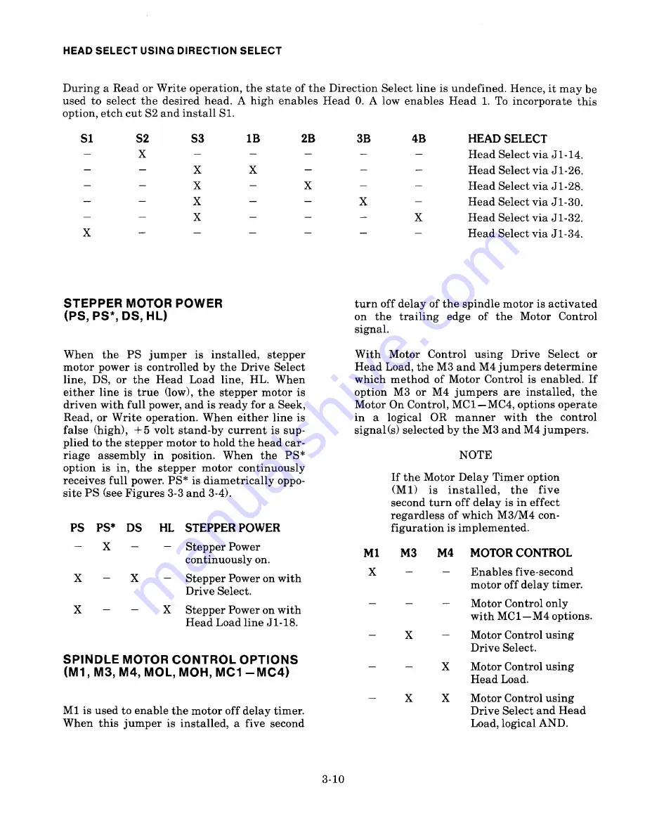
HEAD SELECT USING DIRECTION SELECT

During  a  Read or  Writ e  operation,  the  state of  the  Direction  Select  line  is  undefined.  Hence, it  may  be

used to select 

the desired head. A high enables Head 0. A low enables Head 1. To incorporate this

o ption, etch cut S2 and install  Sl .

S1

S2

X

S3

1B

2B

3B

4B

X

X

X

X

HEAD SELECT

Head Select via  J1-14.

Head Select via  J1-26.

Head Select via  J1-28.

Head Select via  J1-30.

Head Select via  J1-32.

Head Select via  J1-34.

X

STEPPER MOTOR POWER

(PS, PS*, DS, HL)

turn  off  delay of  the  spindle  motor  is  activat ed
o n  th e  t r a i l i n g  e d g e  o f  t h e  M o t o r  C o n t r o l
signal.

W ith  M o t o r  C o n t r o l  u s i n g  D r i v e  S e l ec t  o r
Head Load, the M3  and  M4  jum pers determine
which  method  of  M o tor  Control  i s  enabled.  If
o ption  M 3  o r  M 4  j u m p e r s  ar e i n s t a l l ed,  t h e
Motor On Control,  MC1 — MC4, options operate
i n  a 

l o g i c a l  O R  m a n n e r  w i t h  t he  c o n t r o l

signal(s) 

selected by the M3 and M4 jumpers.

When  t h e 

P S  j u m p e r  i s  i n s t a l l ed ,  s t epper

motor  power  is  controlled  by  th e  D r iv e  Select
l ine,  DS,  or  t h e  H e a d  L o a d  l i n e ,  H L .  W h e n
e ither  l in e  i s  t r u e  ( l o w),  th e  stepper  motor  i s
driven  with  f ul l  power, and is ready  for a Seek,
R ead, or  Wr it e  operation.  When  eit her  l i n e  i s
false  (high),  + 5  v o l t  s t a n d-by  curr ent  i s  sup-

plied to 

the stepper motor to hold the head car-

r iage  assembly  i n 

p o s i t i on . W h e n  t h e  P S *

option  i s  i n ,  t h e  s t e pper  m o tor  c o n t i n u ously
receives full  power.  PS*  is  diametrically  oppo-
site PS (see Figures 3-3 and 3-4).

NOTE

If the  Motor  Delay  Ti mer  option

(M1) 

i s  i n st a l l e d ,  t h e  f iv e

second turn  off  delay  is  in  effect

regardless of which  M 3 /M 4  con-

figuration  is  implemented.

X

-

X

X

X

-

-

X

SPINDLE MOTOR CONT ROL  OPTIONS

(M1, M3, M4, MOL, MOH, MG1 — MG4)

PS  PS~  D S 

HL  STE P PER POWER

Stepper Power
continuously  on.

Stepper Power on with
Drive Select.

Stepper Power on with
Head Load line  J1-18.

X

X

X

M1 

M3 

M4 

MOTO R C ONTROL

Enables five-second

motor off 

delay timer.

Motor Control  only
with  MC1 — M4 options.

Motor Control  using
Drive Select.

Motor Control  using
Head Load.

Motor Control  using
Drive Select and Head
Load, l ogical AND.

Ml  is  used to enable the motor  off  delay  tim er.
When  thi s  j u m per  i s  i n s t a l l ed,  a  f i v e  second

3-10

Summary of Contents for TM848-1E

Page 1: ...TN84 5 i 48 2E FLEXISLK 9I8g j RIVES MJ 4 il PRODUCT SPE IFICATION AND USER S MANUAL...

Page 2: ...en approval of Tandon Corporation This document isintended to provide the user with detailed information adequate for the efficient installation operation and service of the equipment involved However...

Page 3: ...E TM848 2E THINLINE FLEXIBLE DISK DRIVE 48 TRACKS PER INCH PRODUCT SPECIFICATION AND USER S MANUAL lcllld D I 1CORPORATION CHATSWORTH CALIFORNIA 91311 20320 PRAIRIE STREET o COPYRIGHT 1983 TANDON CORP...

Page 4: ...ns Reliability Specifications Environmental Specifications 2 1 2 1 2 1 2 1 2 1 3 4 3 1 3 2 3 3 2 1 2 2 2 3 2 4 SECTION 3 OPER ATION Introduction Unpacking The Drive Preinstallation Checkout Mounting T...

Page 5: ...aracteristics Control and Data Timing Requirements LSI Circuit Board Assembly Non LSI Circuit Board Assembly Recording Media Diskette Care and Handling 1 4 2 2 2 5 2 5 3 6 3 7 3 11 3 12 3 17 3 18 3 1...

Page 6: ...a t a s t o rage The M o del TM848 2E drive doubles data storage capabili ties by using both sides of the diskette 1 1 SCOPE OF THE DOCUMENT 1 3 MA JOR FEATURES MICROPROCESSOR CONTROL The TM848 1E an...

Page 7: ...i v ates t h e cone clamp system r esulting in acc u r ate centering and clamping of the diskette to the drive hub The drive hub is driven at a con s tant s peed o f 360 RPM by a cry st a l controlled...

Page 8: ...n fr o m Track 0 or Tr a c k 0 sensor is always equal to zero The spindle is rotated by a direct drive brush less D C motor with an integral tachometer T he cr y stal controlled s e rv o c i r cuit an...

Page 9: ...GURp y y OISK Qp yp...

Page 10: ...contains the physical dimensions of the drive 2 2 ELECTRICAL AND OPERATIONAL SPECIFICATIONS The electrical and operational specifications are located in Table 2 1 2 3 RELIABILITY SPECIFICATIONS The re...

Page 11: ...19 0 MM 1 60 40 6 MM 25 4 MM 7 50 190 5 MM 1 650 41 5 MM 0 52 13 2 MM 8 550 217 2 MM 2 025 51 4 MM 2 300 58 4 MM NOTES 1 DIMENSIONS ARE GIVEN IN INCHES METRIC EQUIVALENTS ARE IN PARENTHESES 2 TOLERANC...

Page 12: ...ilinches 51 50 millimeters 2 03 inches 49 42 millimeters 1 95 inches Both Drives TM848 2E Side 1 91 75 millimeters 3 61 inches 89 64 millimeters 3 53 inches 15 000 media contact hours Head Life Disk R...

Page 13: ...percent at 700 milliamperes typical For surge current requirements see Figures 2 2 and 2 3 5 volts 5 percent at 450 milliamperes typical 5 volts D C Power Typical Current Requirements For 24 volts D C...

Page 14: ...FIGURE 2 2 24 VOLT D C CURRENT CONFIGURATION 1 Configured for stepper motor disabled until motor comes up to speed 1 8 amps typical surge STEPPER MOTOR ENABLED C 2 5 U R 2 0 1 5 E N 10 T 0 5 I N 50 10...

Page 15: ...t s One in 10 seeks 10 000 power on hours 30 minutes Mean Time Between Failures Mean Time To Repair TABLE 2 3 ENVIRONMENTAL SPECIFICATIONS Temperature 4 4 C to46 C 40 F to 115 F 40 C to 71 C 40 F to 1...

Page 16: ...e upright horizontal or vertical When mounted horizontally the Logic circuit board side of the chassis must be the top side Eight holes areprovided for mounting two on each side and four on the botto...

Page 17: ...r ough the d r i v e nr h eads a n d diskettes 1 Direction 2 Step 3 Write Data 4 Write Gate 5 In Use 6 Side Select TM848 2E only 7 Write Current Switch 8 Head Load 3 4 INTERFACE CONNECTIONS MOTOR ON...

Page 18: ...state of the Direction Select line when a step pulse is issued The motion is toward the center ofthe disk ifthe Direction Select line is in the true low state The direc tion of motion is away from the...

Page 19: ...5 When the diskette lever is opened NOTE C hanges of state of th e W r i t e Gate line should occur before the first Write Data pulse COMPOSITE WRITE DATA IN USE When the drive is selected this interf...

Page 20: ...ad Data and Ready The strappable output sig nals are Disk Change Two Sided and True Ready READY INDEX The Ready interface signal indicates a disk ette has been inserted into the drive Ready w ill not...

Page 21: ...d r ive has gone to a Ready condition 48 milliamperes maximum V F a l se 2 4 volts minimum open microamperes maximum collector at I 250 Figure 3 1 contains the electrical interface characteristics Fig...

Page 22: ...ILLISECONDS MINIMUM 18 MILLISECONDS TRUE READY WRITE GATE 100 MICROSECONDS MINIMUM 9n sgI I I I S E A A NAP E N S I M I NIMUM I SEE NOTE 4 MICROSECONDS MAXIMUM I WRITE DATA 16 MILLISECONDS MINIMUM 50...

Page 23: ...nd option strapping is determined by the different jumper configura tions required for s pecific system applica tions If jumper configurations are changed power should be cycled off and on so the micr...

Page 24: ...ignal High True Motor Control Select Ready True Ready Lever Lock Solenoid In Use Lever Lock Option In Use Latched In Use Not Latched Disk Change Two Sided Diskette Installed Inhibit Write When Write P...

Page 25: ...is controlled by the Drive Select line DS or the Head Load line HL When either line is true low the stepper motor is driven with full power and is ready for a Seek Read or Write operation When either...

Page 26: ...cted via J1 4 Motor Controlselected via J1 6 Motor Controlselected via J1 8 Motor Control selected via J1 24 X OONL U7 OOMOH 4S Ooo DS4 3S OOO DS3 2S Ooo DS2 I S oOO DS I Oo R Oo D Oo S3 OO S2 Oo S I...

Page 27: ...OO 0 MOH 0 0 MDL OWP 0 ONP 4 B 00 0 D S4 3 B 00 0 D S 3 2 B 00 0 D S 2 I B 00 0 D S I 00 R 00 D 00 S3 0 0 S 2 0 0 S I 0 0 D C 0 0 2 S 0 0 T R 00 MC4 00 MC3 00 MC2 00 MC I 0 0 I C 0 0 X C 0 PS tpl LOJ...

Page 28: ...r ue signal t o t h e controller i n dicating t h a t a doub l e sided diskette i s i ns t alled i n dex h ol e t wo i s present This option is factory installed 2S TW O SIDED DISKETTE LEVER LOCK OPTI...

Page 29: ...s allow the user to test some aspects of drive operation without the use of special test equipment The programs allow the user to isolate the problems of the drive The diagnostic mode provides 16 test...

Page 30: ...motor This test seeks the carriage to Track 76 and turns on the spindle motor This test may be used to check index to data burst and azimuth Seek to Track 75 and turn on spindle motor This test seeks...

Page 31: ...icall test the Track 0 sensor Monitor the status of the lever position switch This test is used to check the lever position switch The front panel L E D flashes on and off with th e opening and closin...

Page 32: ...A damaged or contami nated diskette can impair or prevent recovery o f data and can r esult i n d a m age t o t h e Read Write heads Figure 3 5 contains an i l l u stration of the physical configurat...

Page 33: ...OP IS ENCOUNTERED RETURN THE DISKETTE TO ITS JACKET WHEN NOT IN USE DO NOT WRITE ON THE JACKET WITH PEN OR PENCIL USE A F E LT TIPPED PEN KEEP THE DISKETTE AWAY F R O M M A G NETIC FIELDS DISKETTES S...

Page 34: ...a n o n CORPORATE OFFICES 20320 PRAIRIE STREET CHATSWORTH CA 91311 TELEPHONE NO 213 993 6644 TELEX NO 194794 TWX NO 910 494 1721 PRINTED IN U S A P N 179049 001A T5007A 5 83...

Reviews: