background image

OPERATING MANUAL 

PLASMA CUTTING

GB

Inglese

GB

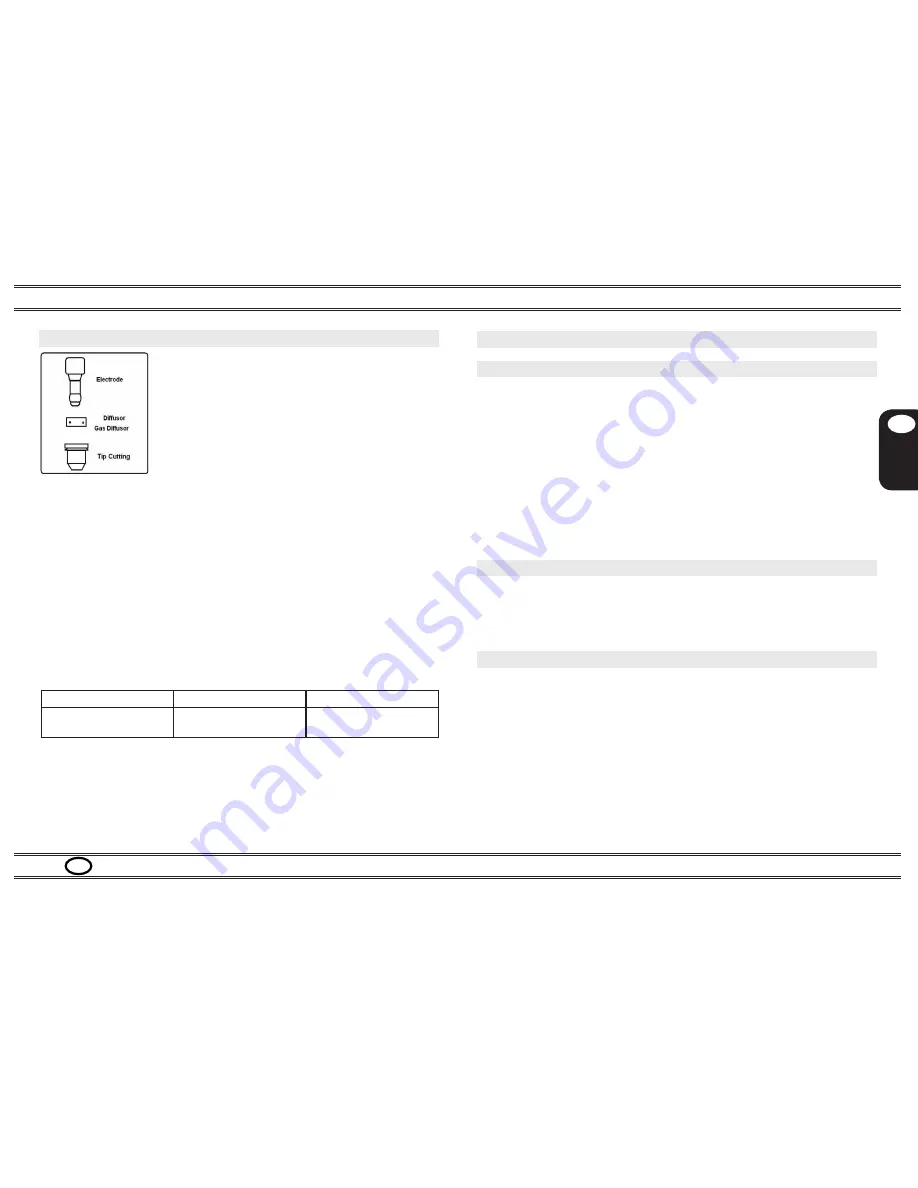
5. Replacing consumer parts


Always shut off the machine before replacing consumer parts.
The electrode must be replaced when it has a crater in the center approximately 1 
mm deep.
The diffuser must be replaced when some areas are blackened. Due to its small 

size, is very important to position it correctly during assembly (see fig. 4).

The gas nozzle or tip cutting must be replaced when the hole is no longer smooth 
and the cutting capacity is diminished.
The nozzle holder must be replaced when the insulating part is deteriorated.
For the best cutting performances, use the following tip cutting-nozzle holder com-
bination ( for order code see Spare part section)

Table 4: spare parts

Current/Model

From 13 to 18 Amp

From 18 to 25 Amp

Site Cut 10

Tip diameter 0,65 mmnoz-

zle holder with 2 holes

Tip diameter 0,8 mmnozzle 

holder with 2 holes

Make sure that the electrode, the diffuser an the gas nozzle are mounted 
correctly, and that the nozzle holder is firmly tightened

If any of this parts are missing, this will interfere with smooth operation of 

the machine and, especially, jeopardize operator safety.

Picture 8 : mouting schematic

6.  Cutting errors

6.1  Insufficient penetration

This error may be caused by the following:

High speed. Always make sure that the arc fully penetrates the workpiece  


and is never held at a forward angle of more than 10-15°. This will avoid   


incorrect consumption of the nozzle and burns to the nozzle holder.
Excessively thick workpiece This inverter cut 

8

 mm. Max and 1

0

 mm.    


severance .
Grounding clamp not in good electrical contact with the workpiece.
Worn nozzle and electrode.
Cutting current too low.
NOTE: when the arc does not penetrate, the molten metal scraps obstruct 

the nozzle.

6.2  The cutting arc goes off

This error may be caused by:

Worn nozzle, electrode or swirl ring.
Air pressure too high.
Supply voltage too low.

6.3  Shorter life of consumer parts

This error may be caused by:

Oil or dirt in the arc intake.
Unnecessarily long pilot arc.
Low air  pressure.

Make sure that the new electrode and nozzle to be mounted are thoroughly clean 
and degreased.
Always use original spare parts to avoid damaging the torch.  


PAGE 7

Summary of Contents for Site Cut 10

Page 1: ...COMPRESSOR PLASMA CUTTING EQUIPMENT OPERATING MANUAL PLASMA CUTTING GB Inglese GB Site Cut 10...

Page 2: ...echnical specifications pag 3 4 Technical specifications table pag 5 4 Star up and use pag 5 4 1 Main supply connection pag 5 4 2 Cutting start up pag 5 5 Replacement consumer parts pag 8 6 Cutting pr...

Page 3: ...mity declaration The machines descripted in this manual Site Cut 10 must be used solely for professional purposes in an industrial environment and they are manufactured in compliance with the instruct...

Page 4: ...CEMAKERS The magnetic fields created by high currents may affect the operation of pacemakers Wearers of vital electronic equipment pacemakers should consult their physician before beginning any arc we...

Page 5: ...mber Always indicate this for any request Single phase static transformer rectifier frequencyconverter inverter Drooping characteristic Suitable for plasma cutting TORCH TYPE Type of torch that may be...

Page 6: ...ved Press the torch trigger to strike the pilot arc Begin cutting as shown in fig 5a avoid starting as shown in fig 5b Further during cutting operation the torch have to keep in contact with workpiece...

Page 7: ...cerning cutting speed vs cutting thickness with cutting current Thickness mm Material Current Amp Speed m min Note The above table has to consider only an example for setting the best parameters The d...

Page 8: ...firmly tightened If any of this parts are missing this will interfere with smooth operation of the machine and especially jeopardize operator safety Picture 8 mouting schematic 6 Cutting errors 6 1 I...

Page 9: ...ve this filter and clean it with low flow air compressed 7 2 Precautions after repairs After making repairs take care to organize the wiring so that there is secure insu lation Do not allow the wires...

Page 10: ...rch head 1a R4929101 O Ring 2 R4924109 Electrode Hf back arc stricking 3 R4622101 Air diffuser 4 R4913130 Tip 0 65 10 20 A back arc stricking R4913131 Tip 0 8 20 30A back arc stricking R4913132 Tip 0...

Page 11: ...OPERATING MANUAL PLASMA CUTTING GB Inglese GB PAGE 10...

Page 12: ...Partita Iva 03377580240 Telefono 39 0444 552887 Telefax 39 0444 284875 Ter s r l Via Madonna delle Grazie 27 Costabissara 36030 Vicenza Internet http www terwelding com e mail info terwelding com...

Reviews: