background image

Summary of Contents for Direct Connect 26-2228

Page 1: ...TANDY Direct Connect Modem Pak OPERATION MANUAL cat no 26 2228...

Page 2: ...n be determined by turning the equipment off and on the user is encouraged to try to cor rect the interference by one or more of the following measures Reorient the receiving antenna Relocate the comp...

Page 3: ...BE CA SED DIRECTLY OR mS 6 1 SPSSSHE S0 LD LEASED LI SED OR FURNISHED BY RADIO SHACK INCLUDING BUT NOT ffi E T D yPc A N BUSINESS 0R ANTICIPATORY PROFITS OR CONSEQUENTIAL DAMAGES SS IK S H IHLUSE 0R...

Page 4: ...dem Pak causes problems on the phone line the telephone company has the right to temporarily discontinue your service If this happens the telephone company will notify you and give you a chance to hav...

Page 5: ...dem Pak 3 2 Installation 5 3 How to use your Modem Pak 9 4 Sample log on session 21 5 Special character codes 23 6 Technical information 25 7 Programming examples 29 8 Troubleshooting and maintenance...

Page 6: ......

Page 7: ...r can be operated without going back into BASIC mode Special codes can be generated to edit transmit data and to create OS 9 characters To use the Modem Pak you ll need a Tandy Color Computer with at...

Page 8: ......

Page 9: ...on 3 CONNECT switch This switch connects the Modem Pak to the telephone line Press this switch to transmit or receive data from the telephone line 4 ANSWER ORIGINATE switch Slide this switch to the AN...

Page 10: ......

Page 11: ...lor Computer Operation Manual or Introducing YOUR COLOR COMPUTER 2 Connecting the Modem Pak to a Color Computer Insert the Modem Pak into the cartridge slot on the right side of the Color Computer or...

Page 12: ...PHONE jack on the Modem Pak and the other end into the duplex jack as shown in Figure 3 Notes 1 With the Modem Pak connected your phone can only be used for conversation when the CONNECT switch is off...

Page 13: ...recorder owner s manual for instructions on connecting these three plugs to a cassette recorder Connecting a printer To connect the Color Computer to a printer you will need a 4 Pin DIN to 4 Pin DIN...

Page 14: ......

Page 15: ...the first page of the menu will be displayed Figure 4 The second page of the menu can be displayed by pressing the f SPACE BAR Figure 5 Upon power up the menu will always show the default settings as...

Page 16: ...ENU Figure 5 Changing communications settings To change one of the communications parameters move the cursor with the arrow keys T and press ENTER or after pressing ENTER enter a new value with the up...

Page 17: ...top bits select either 1 or 2 Auto line feed ON or OFF This option lets you select whether the carriage return will be inter preted on the display as a carriage return and line feed combination auto l...

Page 18: ...different type of computer use XMODEM to avoid transmission errors In XMODEM mode data is divided into blocks of 128 bytes and transmitted with the checksum of that data block Because of this block f...

Page 19: ...back of your computer The second page of the protocol menu Look at the second page of the protocol menu before going into ter minal mode As you may recall all you need to do is press the SPACE BAR to...

Page 20: ...r host computer documentation for details Cassette buffer used Indicates how much cassette buffer space has been used This lets you know the available buffer size left for new data Printer buffer size...

Page 21: ...the true not color reverse lowercase letters noted in the sec tion called Uppercase only lowercase letters set this parameter to ON You can change the OFF condition to ON by pressing ENTER To change...

Page 22: ...ER CLOSED is displayed In the XMODEM mode the message RECE I V I NS X MODEM F I LE appears when you press and T The Modem dues not execute any command except BREAK until the Modem receives data from t...

Page 23: ...e in either mode The ALT function key 5 PRINT is also available from the main menu but its function when selected from the main menu is somewhat different from its opera tion in terminal mode When it...

Page 24: ...essing the RESET switch on the back of your computer 6 To check the data written to the cassette buffer press simultaneously Storing BASIC program data files into the cas sette buffer 1 Before communi...

Page 25: ...sette recorder as described on page 17 Check to be sure the cassette buffer is closed 2 Set up for communication as described in step 3 at lower section on the previous page 3 Press simultaneously The...

Page 26: ......

Page 27: ...data by using the ALT function keys 5 Set the ANSWER ORIGINATE switch to the ORIGINATE po sition the host computer should be in ANSWER mode 6 With the CONNECT switch off out dial the telephone number...

Page 28: ...r the remote computer operator to call you 3 Upon receiving the call press in the CONNECT switch ON and hang up the phone 4 When the carrier detect CD indicator lights begin data communi cations 5 Whe...

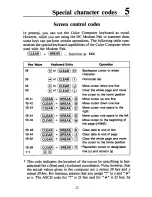
Page 29: ...T CLEAR BREAK y Backspace cursor or erase character Horizontal tab Move cursor down one line Clear the whole page and move the cursor to the home position Move cursor up one line Move cursor down one...

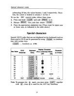
Page 30: ...al characters Special ASCII codes that are not displayed on the keyboard such as those used in OS 9 can be generated by using CLEAR in combina tion with certain keys CLEAR functions as CTRL Hex Value...

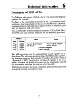
Page 31: ...tions Address Write Read Hex Decimal FF6C FF6D FF6E FF6F 65388 65389 65390 65391 Transmit Data Register Receiver Data Register Soft Reset Status Register Command Register Control Register This table s...

Page 32: ...Self Clearing Receive Data Register Full 0 Not Full 1 Full Read Receive Data Register Transmit Data Register Empty 0 Not Empty 1 Empty Write Transmit Data Register DCD 0 DCD Low 1 DCD High Not Resett...

Page 33: ...led 1 1 1 Space Parity Bit Transmitted Parity Check Disabled NORMAL ECHO MODE FOR RECEIVER 0 Normal 1 Echo Bits 2 and 3 must be 0 DATA TERMINAL READY O Disable Receiver and All Interrupts DTR high 1 E...

Page 34: ...if Word Length 8 Bits and Parity IV2 Stop Bits if Word Length 5 Bits and No Parity This allows for 9 bit transmission 8 data bits plus parity WORD LENGTH BIT DATA WORD LENGTH 6 5 8 1 7 1 6 1 1 5 RECEI...

Page 35: ...Parity ORA 00 MODE Normal ORA 08 Tx Int Disabled RTS Active Tx On ORA 02 IRQ Int Disabled ORA 01 Rx Enabled and All Int STA FF6E Write to Command Register CKMDM LDA To check the Modem Status DSR FF6E...

Page 36: ...s Register TFR A B Save Status ANDA 08 Check if Received Any Data BEQ RXDT Not Received Yet ANDB 07 Received Check Any Error BEQ RXDATA No Error Good Data LSRB Error Check Type of Error BCS PARERR Par...

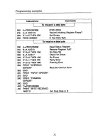
Page 37: ...65390 Y Write to Command Register FF6E HEX 50 To check the Modem Status A PEEK 6 5390 Get Current Command Byte 60 A A OR 1 OR in DTR Enable Bit 65 POKE 65390 A Output New Command Byte 70 B PEEK 65389...

Page 38: ...a byte A PEEK 6 5389 Read Status Register 310 B A AND 8 Receive Register Full 320 IF B 0 THEN 300 No Data Yet 330 E A AND 7 Check for Errors 340 IF E 0 THEN 400 No Errors 350 IF E 1 THEN 370 Parity Er...

Page 39: ...em should be a Bell system 103 or equivalent Garbled display The phone is not on hook Hang up the phone Communications protocol may be set incorrectly baud rate word length parity stop bit Check and c...

Page 40: ...r an incident such as a lightning strike near or directly to these lines may cause an excessive surge of voltage that can damage the phone device Lightning damage is uncommon but it can occur to phone...

Page 41: ...nce specifications Receive frequencies Answer Mark 1270 Hz Space 1070 Hz Originate Mark 2225 Hz Space 2025 Hz Transmit frequencies Answer Mark 2225 Hz Space 2025 Hz Originate Mark 1270 Hz Space 1070 H...

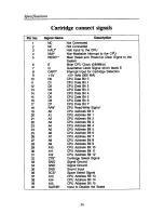
Page 42: ...89MHz Quadrative Clock Signal which leads E Interrupt Input for Cartridge Detection 5V Volts 300 MA CPU Data Bit CPU Data Bit 1 CPU Data Bit 2 CPU Data Bit 3 CPU Data Bit 4 CPU Data Bit 5 CPU Data Bi...

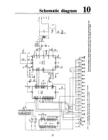
Page 43: ...Schematic diagram 1U B 6 HI B S H o a ll S3 Ht 6 HK HE IS is VW 8 eg n I I f a IS CE I n G3 E IS 3 O O W O O u o 2 t iz 3 O o c D O CO 1 1 S 5 37...

Page 44: ......

Page 45: ...oken Radio Shack reserves the right to refuse to service the product or to void any remaining warranty on the product 2 If any computer product purchased from Radio Shack has been modified so that it...

Page 46: ...ARRIE ONTARIO L4M 4WS AUSTRALIA 91 Kurrajong Avenue Mount Druitt NSW 2770 TANDY CORPORATION BELGIUM FRANCE Rue des Pieds d Alouette 39 5140 Naninne Namur Centre Commercial des 3 Fontaines B P 147 9502...

Reviews: