27
Step 8:
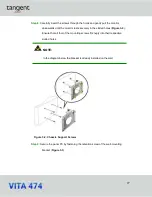
Carefully insert the screws through the holes and gently pull the monitor
downwards until the monitor rests securely in the slotted holes (
Figure 3-2
).
Ensure that all four of the mounting screws fit snugly into their respective
slotted holes.
NOTE:
In the diagram below the bracket is already installed on the wall.
Figure 3-2: Chassis Support Screws
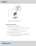
Step 9:
Secure the panel PC by fastening the retention screw of the wall-mounting
bracket (
Figure 3-3
).
Summary of Contents for VITA 474
Page 1: ...tan g ent USER MANUAL...
Page 8: ...8 Chapter 1 Introduction...
Page 20: ...20 Unpacking Chapter 2...
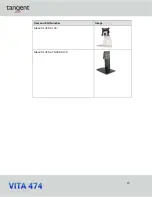
Page 23: ...23 Item and Part Number Image Stand for VESA 100 Stand for VESA 75 VESA 100...
Page 24: ...24 Installation Chapter 3...
Page 34: ...34 BIOS Setup Chapter 4...
Page 70: ...70 Appendix A Regulatory Compliance...
Page 74: ...74 Appendix B Safety Precautions...
Page 80: ...80 Appendix C Watchdog Timer...

